Refrigeration cycle device

a technology of refrigerating cycle and condenser, which is applied in the direction of lighting and heating apparatus, heating types, and domestic hot water supply systems, etc., can solve the problems of deteriorating cooling capacity of evaporators, shortening or lowering the amount of heat to be rejected from refrigerant in the condenser, and causing temperature rise, so as to maintain the cooling capacity of the evaporator, the temperature of the water subjected to the heat exchang

Inactive Publication Date: 2007-08-30
PANASONIC INTELLECTUAL PROPERTY MANAGEMENT CO LTD
View PDF14 Cites 55 Cited by
  • Summary
  • Abstract
  • Description
  • Claims
  • Application Information

AI Technical Summary

Benefits of technology

[0013]According to the second invention, the refrigeration cycle device is provided with the refrigerant circuit including the compressor, the condenser, the throttling means and the evaporator; and the hot water storage tank. The device performs the heat exchange between the water stored in the hot water storage tank and the condenser to generate the hot water by the heat rejected from the condenser and store the hot water in the hot water storage tank. Furthermore, the device exhibits the cooling function by the heat absorption of the evaporator. The device comprises the water supply unit which supplies the water into the hot water storage tank; and the discharge unit which discharges the water from the hot water storage tank. In a case where the temperature of the water stored in the hot water storage tank, the temperature of the water to be circulated through the heat exchanger which performs the heat exchange between the condenser and the water stored in the hot water storage tank, the temperature in the condenser or the temperature of the refrigerant discharged from the condenser rises to the predetermined value or more, the water is discharged from the hot water storage tank by the discharge unit. Therefore, since the water is discharged by the discharge unit, water at a temperature lower than that of the water discharged from the water supply unit to the hot water storage tank can be supplied. Therefore, the temperature of the water subjected to the heat exchange between the water and the condenser can be lowered.
[0014]In consequence, the amount of the heat to be rejected from the refrigerant in the condenser can be secured. Therefore, the cooling capacity of the evaporator can be maintained.
[0015]Moreover, in the second invention, for example, it is assumed that the device includes a high-temperature water takeout port disposed at an upper portion of the hot water storage tank and a low-temperature water takeout port disposed at a lower portion of the hot water storage tank and that the discharge unit is disposed below the high-temperature water takeout port and above the low-temperature water takeout port. In this case, a thermal loss is suppressed as much as possible. Moreover, the use of high-temperature water (hot water) stored in the hot water storage tank is not hindered, the water is discharged from the hot water storage tank by the discharge unit, and the temperature of the water to be subjected to the heat exchange between the water and the condenser can be lowered.
[0016]According to the third invention, the refrigeration cycle device is provided with the refrigerant circuit including the compressor, the condenser, the throttling means and the evaporator, performs the heat exchange between the water and the condenser to generate the hot water by the heat rejected from the condenser, and exhibits the cooling function by the heat absorption of the ev

Problems solved by technology

In a case where the heat is discharged from the condenser to the atmospheric air as in a conventional example, a disadvantage occurs that a temperature rise is caused by the discharged heat around the refrigeration cycle device.
However, in a case where the heat generated in the evaporator as described above is used for

Method used


Image

  • Refrigeration cycle device
  • Refrigeration cycle device
  • Refrigeration cycle device

Examples


embodiment 1

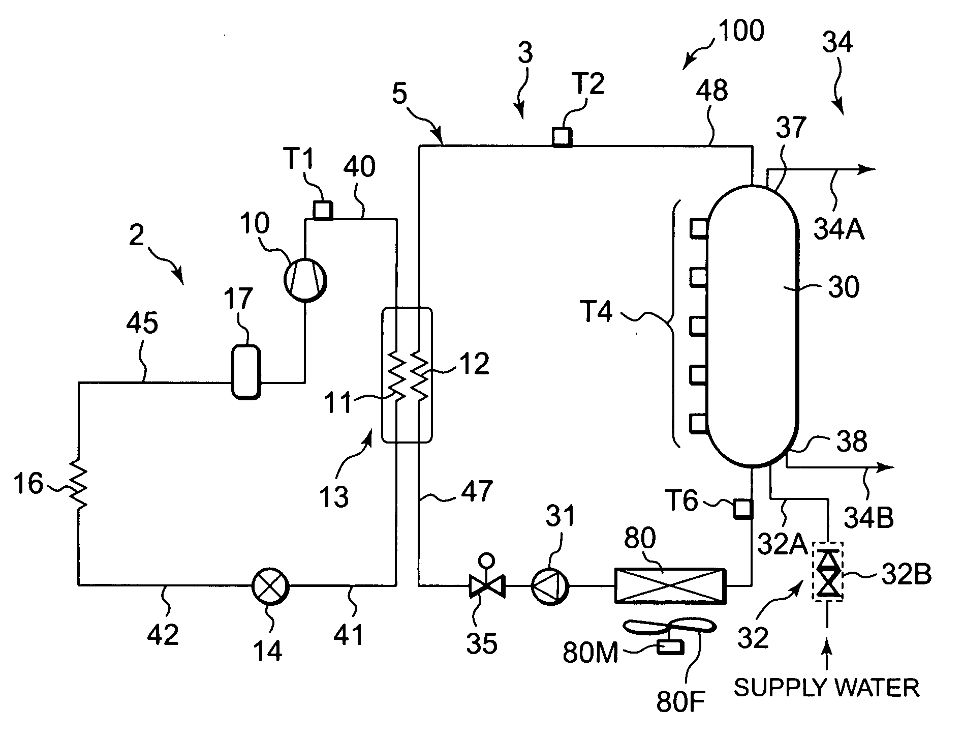
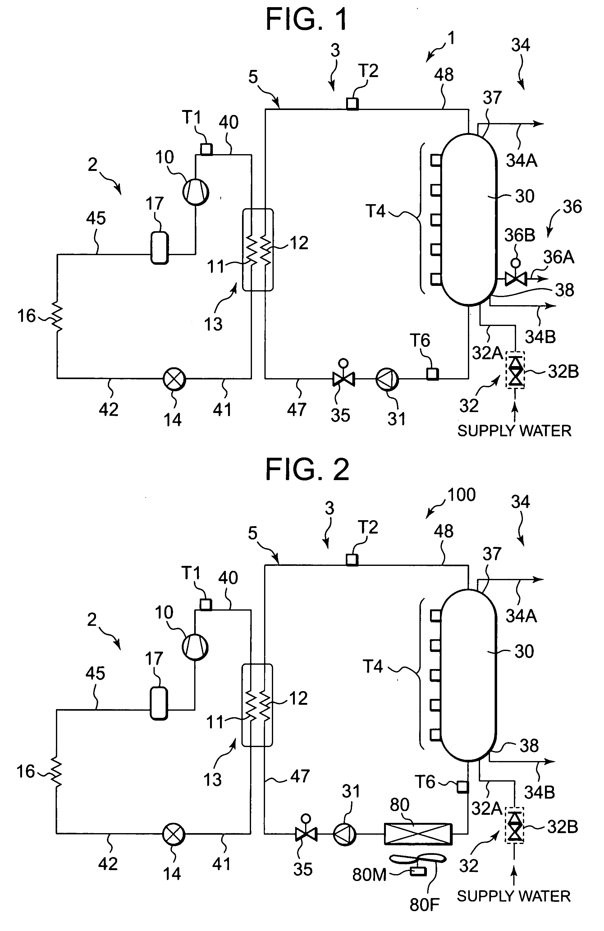
[0027]FIG. 1 is a schematic constitution diagram of a refrigeration cycle device of one embodiment to which the present invention is applied. A refrigeration cycle device 1 of the present embodiment is provided with a refrigerant circuit 2 including a compressor 10, a condenser 11, an expansion valve 14 as a throttling means and an evaporator 16; and a hot water supply circuit 3 including a hot water storage tank 30. The device exhibits a heating function by heat rejected from the condenser 11 and exhibits a cooling function by heat absorption of the evaporator 16. That is, the refrigeration cycle device 1 performs heat exchange between water or hot water circulated from the hot water storage tank 30 through the hot water supply circuit 3 and the condenser 11 to generate high-temperature water by the heat rejected from the condenser 11 and store the hot water in the hot water storage tank 30. Moreover, the device exhibits the cooling function by the heat absorption of the evaporator...

embodiment 2

[0077]Next, another embodiment of a refrigeration cycle device according to the present invention will be described. FIG. 2 is a schematic constitution diagram of the refrigeration cycle device of the embodiment to which the present invention is applied. In FIG. 2, components denoted with the same reference numerals as those of FIG. 1 are the same components or components which produce similar functions or effects. Therefore, description thereof is omitted, and a part of the present embodiment different from the above embodiment will mainly be described.

[0078]First, a difference between a constitution of a refrigeration cycle device 100 of the present embodiment and that of the refrigeration cycle device 1 of Embodiment 1 will be described. The refrigeration cycle device 1 of Embodiment 1 includes a discharge unit 36 which discharges hot water from a hot water storage tank 30 as needed. On the other hand, the refrigeration cycle device 100 of the present embodiment does not include ...

embodiment 3

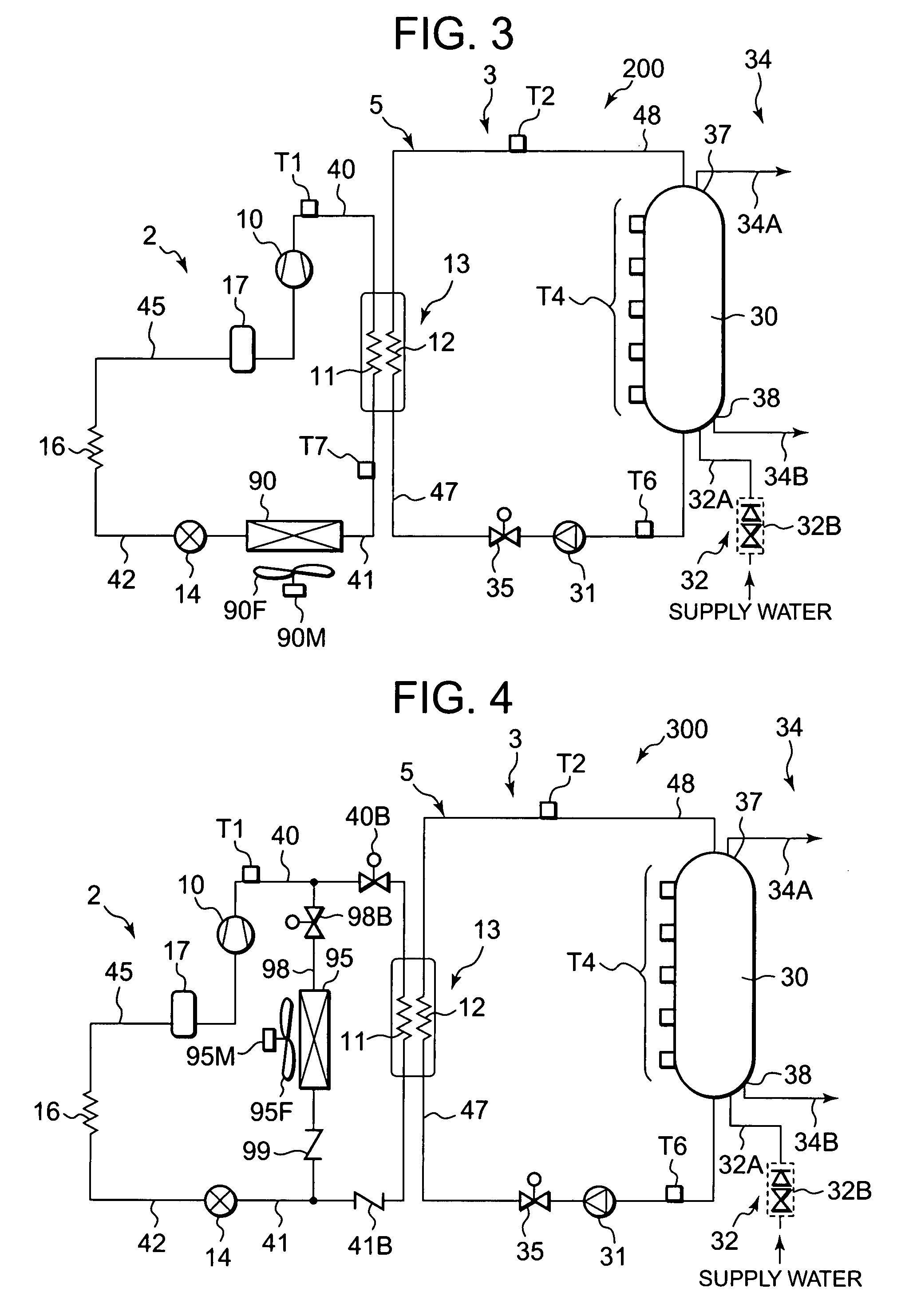
[0093]Next, still another embodiment of a refrigeration cycle device according to the present invention will be described. FIG. 3 is a schematic constitution diagram of the refrigeration cycle device of Embodiment 3 to which the present invention is applied. It is to be noted that in FIG. 3, components denoted with the same reference numerals as those of FIGS. 1 and 2 are the same components or components which produce similar functions or effects. Therefore, description thereof is omitted, and a part of the present embodiment different from the above embodiments will mainly be described.

[0094]First, a difference between a constitution of a refrigeration cycle device 200 of the present embodiment and that of the refrigeration cycle device 1 of Embodiment 1 will be described. The refrigeration cycle device 1 of Embodiment 1 includes a discharge unit 36 which discharges hot water from a hot water storage tank 30 as needed. On the other hand, the refrigeration cycle device 200 of the p...


PUM


Abstract

In a refrigeration cycle device in which heat generated by heat absorption of an evaporator is used for heating in a condenser, a disadvantage that a cooling capacity of the evaporator deteriorates owing to shortage or drop of an amount of the heat to be rejected from the condenser is securely avoided and a cooling function is maintained. In the refrigeration cycle device which is provided with a refrigerant circuit including a compressor, a condenser, an expansion valve and an evaporator and which exhibits a heating function by the heat rejected from the condenser and which exhibits the cooling function by the heat absorption of the evaporator, an operation to secure a predetermined amount of the heat to be rejected from the condenser is executed in order to maintain the cooling function of the evaporator based on an index capable of grasping the amount of the heat to be rejected from the condenser.

Description

BACKGROUND OF THE INVENTION[0001]The present invention relates to a refrigeration cycle device provided with a refrigerant circuit including a compressor, a condenser (or condensing heat exchanger or gas cooler or gas cooling heat exchanger), a throttling means and an evaporator. The present invention more particularly relates to a refrigeration cycle device which exhibits a heating function by heat rejected (or transferred) from a condenser and which exhibits a cooling function by heat absorption of an evaporator.[0002]Heretofore, as methods such as cooling and freezing to cool an object to be cooled, a refrigeration cycle device has broadly been used in which a vapor compression type refrigeration cycle (vapor-compression refrigeration cycle) is used. This type of refrigeration cycle device exhibits a cooling function by absorbing heat of a refrigerant in an evaporator to cool the object to be cooled, and rejects the heat generated by heat rejected from the refrigerant in a conden...

Claims


Application Information

Patent Timeline
IPC IPC(8): F25B39/04F25B27/00
CPCF24D17/02F25B6/02F25B6/04F25B9/008F25B29/003F25B2700/21163F25B2309/061F25B2339/047F25B2700/2111F25B2700/21152F25B2700/21161F25B49/027
Inventor OTAKE, MASAHISASATO, KOJIMUKAIYAMA, HIROSHI
Owner PANASONIC INTELLECTUAL PROPERTY MANAGEMENT CO LTD
Why Eureka
Try Eureka