Device and method for detecting the position and the velocity of a test object

a technology of test object and position, applied in the direction of devices using electric/magnetic means, instruments, stray field compensation, etc., can solve the problems of large dimensioning of the sensor, affecting the output signal in differentiating systems in general, and the strong restriction of the sensor structure, so as to achieve the optimal ratio of measuring area and maximum linearity of output signals. , the effect of saving spa

Inactive Publication Date: 2007-08-30
MICRO EPSILON MESSTECHNIK GMBH & CO KG
View PDF4 Cites 4 Cited by
  • Summary
  • Abstract
  • Description
  • Claims
  • Application Information

AI Technical Summary

Benefits of technology

[0015] According to the present invention, it was realized at first that a device for determining the position and the velocity of a test object can be designed in a particularly effective and space-saving manner if both the position and the velocity are measured simultaneously using one sensor. According to the present invention, it was further realized that by means of a special design form of the target of an eddy current sensor, it is possible to generate a signal which contains both a position-dependent and a velocity-dependent component and that these components can be derived from the sensor signal by means of a simple evaluation circuit.
[0016] A target (e.g., transducer) is placed on the test object, while being electromagnetically coupled to the measuring coil, wherein the target is formed of two parts according to the present invention, one part being made of an electrically conductive material and the other part consisting of a magnet. According to the present invention, in this device advantage is taken of the fact that the relative movement between the magnet and the measuring coil results in an induction voltage Uv, which is used as a measure of the velocity of movement. Simultaneously, a voltage signal Up resulting from the impedance change of the measuring coil, said impedance change being brought about by the electrically conductive part of the target, is used as a measure of the target position.
[0017] In a preferred design form of the device according to the present invention, the length of the entire target does not exceed the distance between two adjacent voltage taps of the measuring coil and is preferably approximately equal to this distance. An optimal ratio of measuring area to the length of the measuring coil and a maximum linearity of the output signals are thus achieved.

Problems solved by technology

The disadvantage here is the large dimensioning of the sensor.
What proves to be disadvantageous here is the strongly restricted structure of the sensor and the determination of the speed from the course of the armature position over time.
The crucial disadvantage of the methods known from practical experience for determining the velocity from the displacement signal by differentiating the signal is that disturbances particularly noise, greatly influence the output signal in differentiating systems in general.
Thus there are a strongly increasing number of requirements made of the quality of the displacement signal, particularly in relation to linearity and the signal-to-noise ratio, thereby necessitating the use of expensive low-noise sensors.
However, in doing so, the space required and the costs of the sensor system increase considerably due to the sensors and the evaluation electronic systems required in each case.
Furthermore, an additionally necessary synchronization of the two sensors has negative effects.

Method used


Image

  • Device and method for detecting the position and the velocity of a test object
  • Device and method for detecting the position and the velocity of a test object
  • Device and method for detecting the position and the velocity of a test object

Examples


Embodiment Construction

[0032] The present invention now will be described more fully hereinafter with reference to the accompanying drawings, in which some, but not all embodiments of the invention are shown. Indeed, the present invention may be embodied in many different forms and should not be construed as limited to the embodiments set forth herein; rather, these embodiments are provided so that this disclosure will satisfy applicable legal requirements. Like numbers refer to like elements throughout.

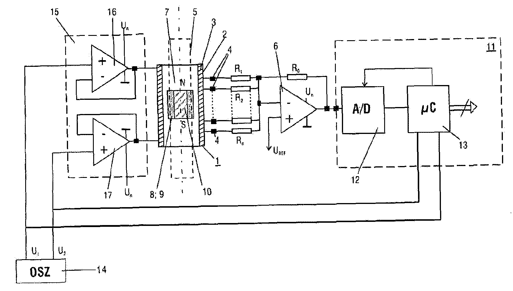
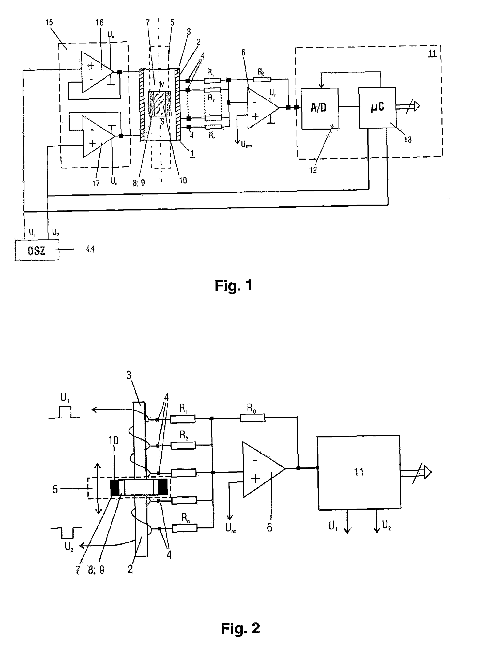
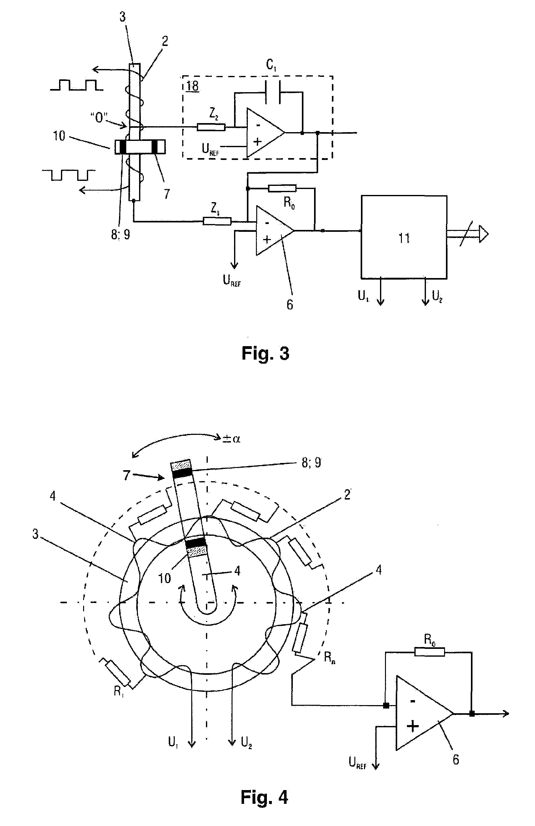
[0033] In a first exemplary embodiment of a device (FIG. 1) according to the present invention, a sensor 1 is provided which comprises a measuring coil 2 which is wound on a coil body 3 and has a number of taps 4. In the interior of the coil body 3, a test object 5 is displaced together with a target 7, which is electromagnetically coupled to the measuring coil 2, along the longitudinal axis of the measuring coil 2. The target 7 is composed of two parts, the first part facing the coil being produced in th...


PUM


Abstract

A device and method for detecting the position and velocity of a test object relative to a sensor, the sensor and the test object being arranged such that they can be displaced relative to one another. In one embodiment, the sensor has a measuring coil with one or more voltage tap(s) and has a target that is placed on the test object while being electromagnetically coupled to the measuring coil. An electronic component for adding the voltages tapped on the sensor is assigned to the sensor. The invention is, with regard to a simplest possible design of the sensor, characterized in that for simultaneously measuring position and velocity, the target comprises two parts, one part being made of an electrically conductive material and the other part being provided in the form of a magnet, and in that an evaluation circuit determines, based on the output signal of the electronic component for adding the tapped voltages, a voltage component Up that is proportional to the position of the target, and a voltage component Uv that is proportional to the velocity of the target.

Description

CROSS REFERENCE TO RELATED APPLICATION [0001] The present application is a continuation of international application PCT / DE 2005 / 001274, filed 19 Jul. 2005, and which designates the U.S. The disclosure of the referenced application is incorporated herein by reference. BACKGROUND OF THE INVENTION [0002] The present invention relates to a device and a method for detecting the position and velocity of a test object relative to a sensor, the sensor and the test object being arranged such that they can be displaced relative to one another, wherein the sensor has a measuring coil with at least one, or preferably a number of voltage tap(s) and has a target, which is placed on the test object while being electromagnetically coupled to the measuring coil and wherein an electronic component for adding the voltages tapped on the sensor is assigned to the sensor. [0003] Measuring devices of the type mentioned above are required, for example, for determining the position of the piston on pneumat...

Claims


Application Information

Patent Timeline
Patent Type & Authority Applications(United States)
IPC IPC(8): G01P3/42
CPCG01D5/2033G01D5/202
Inventor SELLEN, MARTINMEDNIKOV, FELIXNECHAEWSKIJ, MARK
Owner MICRO EPSILON MESSTECHNIK GMBH & CO KG
Why Eureka
Try Eureka