System and method for multiple-phase clock generation

a clock generation and multi-phase technology, applied in the field of clock generation technology, can solve the problems of phase errors in interpolated clocks, limit the frequency of operation of oscillators, asymmetric waveforms, etc., and achieve the effect of simple circuitry

Active Publication Date: 2007-08-30
STMICROELECTRONICS PVT LTD
View PDF8 Cites 14 Cited by
  • Summary
  • Abstract
  • Description
  • Claims
  • Application Information

AI Technical Summary

Benefits of technology

[0011] An object of the present invention is to provide a system and method for generating symmetric clock pulses o

Problems solved by technology

Difference in parasitic capacitances may result in asymmetric waveforms.
This in turn limits the frequency of operation of the oscillator.
However, this technique generates phase errors in the interpolated clocks.
Any mismatch during the entire process

Method used


Image

  • System and method for multiple-phase clock generation
  • System and method for multiple-phase clock generation
  • System and method for multiple-phase clock generation

Examples


Embodiment Construction

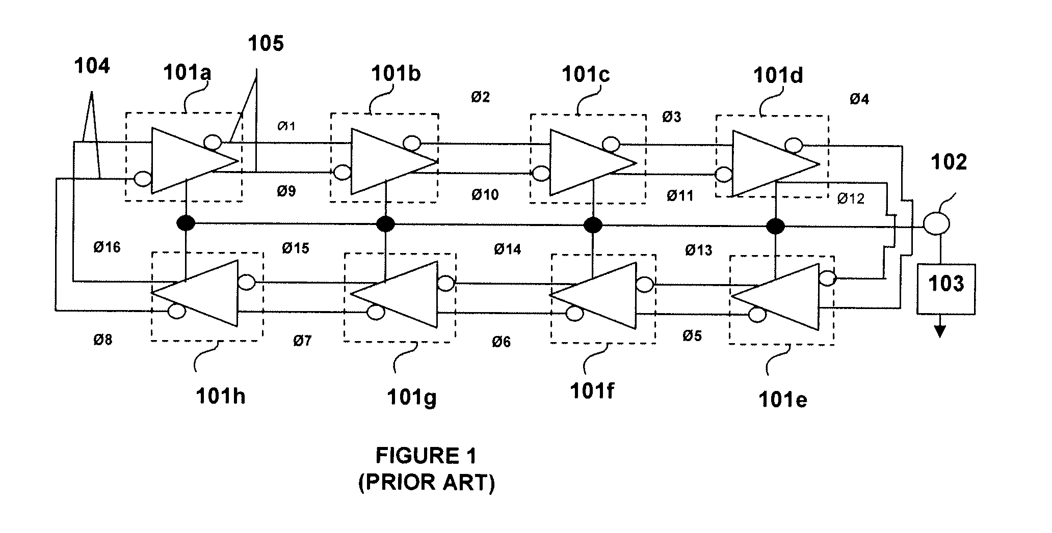
[0022]FIG. 1 shows a voltage controlled differential ring oscillator used for generating multiphase clock signals. It includes N stages (in this embodiment 8 stages) of delay differential inverting amplification circuits (101a, 101b, . . . 101h) connected in the form of a ring and control terminal (102) for controlling the delay time in the delay differential inverting amplification circuit of each stage. Connected to the control terminal is a control voltage source (103). The delay differential inverting amplification circuit of each stage has a differential input terminal pair (104) and a differential output terminal pair (105) where each pair consists of an inverting and a non inverting terminal. The differential output terminal pair (105) of an amplification circuit is connected to the differential input terminal (104) of the next amplification circuit in such a way that a noninverting output terminal of the previous stage is connected to an inverting terminal of the subsequent ...


PUM


Abstract

A multiple phase clock circuit includes a multiple stage voltage controlled oscillator (VCO) and multiple clock dividers. The VCO is operative at a frequency ‘N’ times higher than the required output frequency and generates ‘M’ equally spaced outputs having different phases but same frequency which are sent to multiple clock dividers. A modified Johnson counter is used as a clock divider. Each counter divides the frequency of the clock signal by N. As a result, each of the M outputs of the VCO are divided into N outputs, thereby making a total of ‘M×N’ equally spaced outputs. These output clock pulses have same frequency but different phases. A sequential logic is provided within the device for enabling the Johnson counters as soon as the VCO starts giving output, thus maintaining the sequence of the output of the Johnson counters.

Description

RELATED APPLICATIONS [0001] The present application claims priority of India Patent Application No. 3550 / Del / 2005, first filed Dec. 30, 2005 as a provisional application, for which a complete specification was filed Dec. 22, 2006, said applications being incorporated herein in their entireties by this reference. FIELD OF INVENTION [0002] The present invention relates to the field of clock generation technology and more particularly to a system and method for multiple-phase clock generation. BACKGROUND OF THE INVENTION [0003] Clock signals are used by complex sequential digital circuits to synchronize the operation of the circuit and perform its operations in an orderly manner. These signals are periodical signals with known timing. The timing provides the reference at which the state of the digital system is changed. The use of clock signals allows coherent functioning of the entire circuit design. The clock signal may be distributed over the circuit design and used by all storage e...

Claims


Application Information

Patent Timeline
IPC IPC(8): H03K3/03
CPCH03K3/0315H03K5/15013H03K5/15026H03L7/0995H03K2005/00241H03K2005/00247H03L7/095H03K5/1506H03K3/03Y10S331/02
Inventor SEN, TANMOYKUMAR, ANANDJAIN, DEEPENDRA KUMAR
Owner STMICROELECTRONICS PVT LTD
Why Eureka
Try Eureka