
Marine light mounting system and method for producing same

a technology for mounting systems and light fixtures, which is applied in fixed installation, transportation and packaging, light and heating equipment, etc. it can solve the problems of not being able to electrically disconnect the conductor wire, not being able to facilitate the vehicle operator, and navigation lights that do little to aid the vehicle operator, etc., to facilitate the entry facilitate the attachment of the light housing, and facilitate the effect of connecting and disconnecting faster

Inactive Publication Date: 2007-08-30
HURLEY TODD R
View PDF9 Cites 14 Cited by
  • Summary
  • Abstract
  • Description
  • Claims
  • Application Information

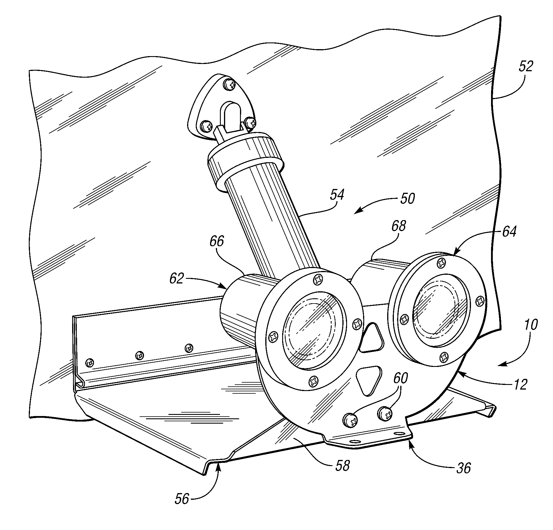
AI Technical Summary

Benefits of technology

[0010] The present invention provides a marine light mounting system, and a method for producing such a system, that provides flexibility with regard to the mounting orientation of a support structure, along with the ability to attach and detach one or more lights without the need to electrically disconnect the lights either from the lamp fixture or the electrical power source.
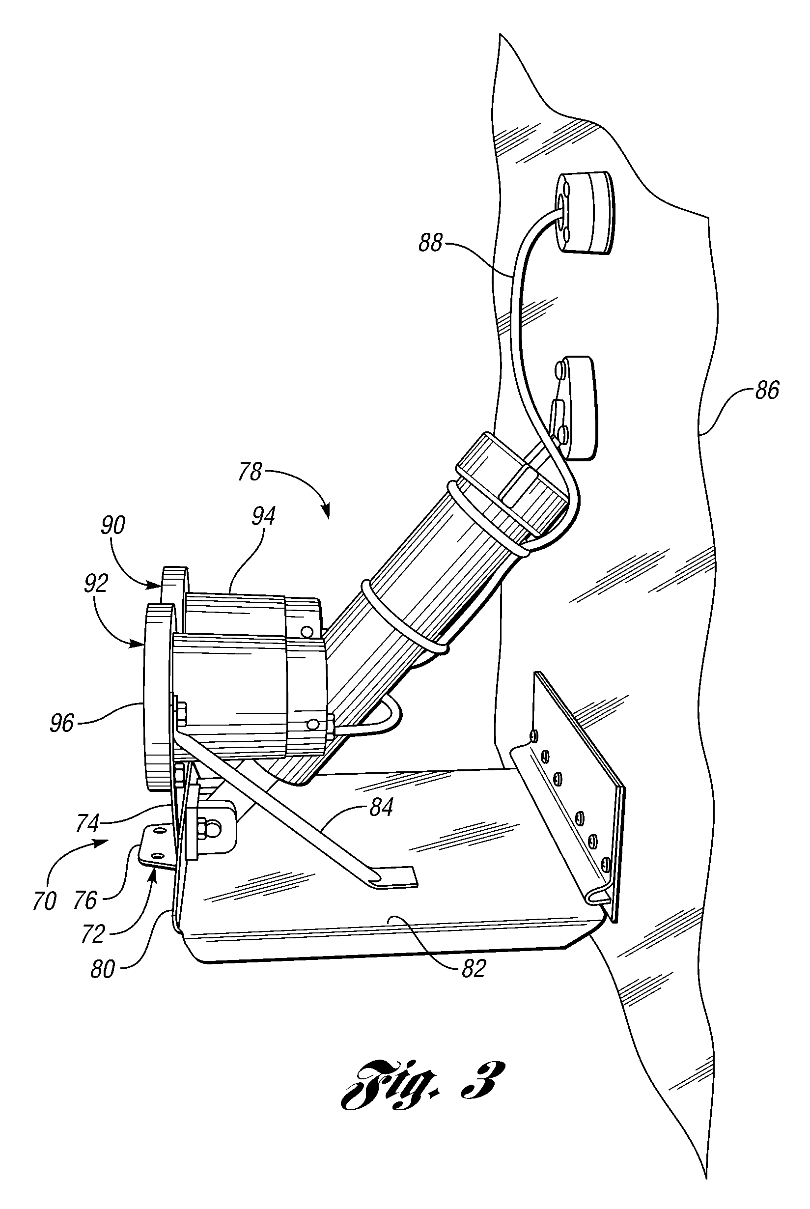
[0011] Embodiments of the present invention provide a mounting bracket that can be attached at various locations on a marine vehicle, such as a boat. In particular, the bracket may be attached to a trim tab on a boat. This provides lighting at the stern of the boat that may be useful for general visibility, as well as in specific situations, such as night fishing, or trailering a boat when it is dark. In addition, attaching the bracket to the trim tab of the boat allows the direction of the light to be changed as the trim tab is moved up or down. Thus, as the trim tab is moved downward, the lights may be submerged and provide underwater lighting.
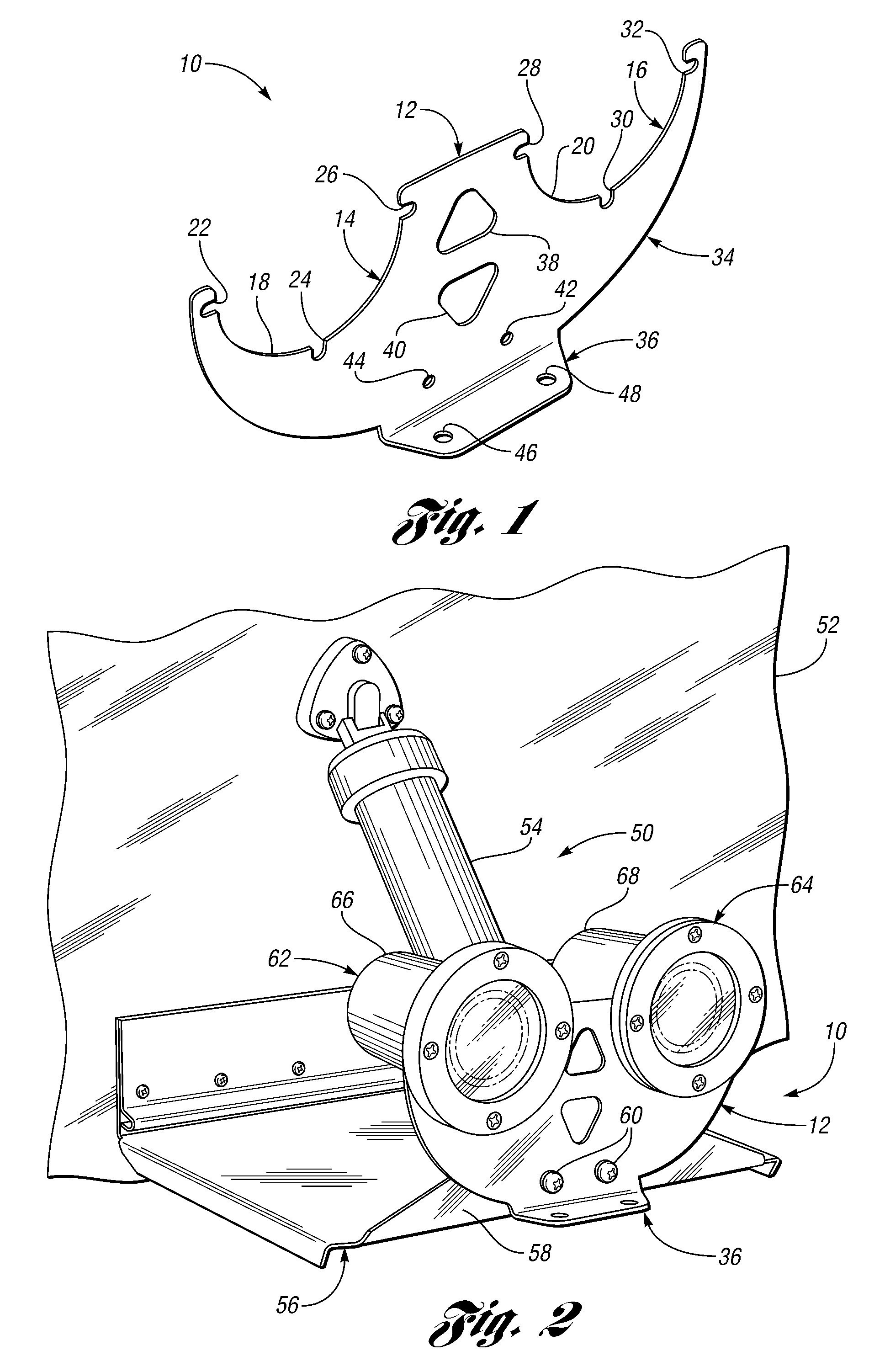
[0012] Embodiments of the invention also provide a bracket such as described above that includes an outwardly extending tab that is configured to be oriented substantially parallel with a surface of the trim tab. The outwardly extending tab may, in effect, provide an extension to the trim tab, thereby providing increased plane control to the vehicle operator. In addition, the tab may be used as a secondary mounting feature to facilitate attachment of the bracket either to the trim tab, or in other locations. One embodiment of the mounting system includes a bracket having two partially circular mounting portions, configured to receive cylindrical light housings. The use of the partially circular geometry allows the light housings to be inserted into the bracket without having to disconnect the electrical wires. This is in contrast to a bracket that is configured with a hole to receive the cylindrical light housing, because in such a case, the wire would have to be disconnected from the lamp or from the power source in order to feed the wire through the hole in the bracket. Such is not the case in embodiments of the present invention. This provides flexibility with regard to the mounting of the support bracket, and subsequent moving of the bracket to different positions on the boat. Because the lights can be quickly disconnected from the bracket, they can be moved separately, and the bracket can be repositioned without interference from the electrical wiring.

Problems solved by technology

These types of navigation lights do little to aid the vehicle operator to see objects in low visibility conditions.
One limitation of the marine lamp described in Perkins is the need to electrically disconnect the conductor wire from either the lamp or its power source in order to feed the conductor wire through the openings in the cap and gasket.
This is not possible with the Perkins design, since it is the light housing that attaches directly to the boat.
Even if it were possible, however, changing the orientation of the light vis-à-vis the housing would require electrically disconnecting the conductor wire from either the light fixture or the power source.
Such an operation may be time consuming and difficult, assuming it can be performed at all.

Method used


Image

  • Marine light mounting system and method for producing same
  • Marine light mounting system and method for producing same
  • Marine light mounting system and method for producing same

Examples


Embodiment Construction

)

[0026]FIG. 1 shows a marine light mounting system 10 in accordance with one embodiment of the present invention. The mounting system 10 includes a support structure, or bracket 12. The bracket 12 includes a pair of light mounting portions 14, 16. The light mounting portions 14, 16 respectively include curved surfaces 18, 20 that are configured to cooperate with a housing on a marine light when the housing is attached to the bracket 12. As described more fully below, when lights are attached to the bracket 12, the surfaces 18, 20 will be adjacent to only a portion of the corresponding housing. This provides advantages over a closed surface such as would be formed if the light mounting portions 14, 16 formed full circles, instead of having a contour that forms partial circles as shown in FIG. 1. Although shown in FIG. 1 as forming partial circles, it is understood that other embodiments of the present invention may have light mounting portions that have non-circular contours, such as...


PUM


Abstract

A marine light mounting system for attaching at least one light to a marine vehicle includes a support structure for supporting one or more lights on the marine vehicle. The support structure includes a light mounting portion configured to receive a housing of one of the lights, and to facilitate attachment of the housing to the support structure. The light mounting portion includes a surface that may be generally arcuate, and which is configured to cooperate with the housing such that the surface does not completely surround a housing of the light. This facilitates attachment of the housing to the support structure while the light is electrically wired to a power source remote from the housing. This provides flexibility with regard to mounting the light in the first instance, and changing the orientation of the bracket in the second.

Description

CROSS-REFERENCE TO RELATED APPLICATIONS [0001] This application claims the benefit of U.S. provisional application Ser. No. 60 / 888,820, filed Feb. 8, 2007, which is hereby incorporated herein by reference.BACKGROUND OF THE INVENTION [0002] 1. Field of the Invention [0003] The present invention relates to a marine light mounting system and a method for producing such a system. [0004] 2. Background Art [0005] Owners and operators of watercraft are well aware of the desirability of having a reliable source of light on their vehicle. Bow and stern lights are often required by law; however, these types of lights are primarily used so that operators of other marine vehicles can see approaching vessels, and navigate accordingly. These types of navigation lights do little to aid the vehicle operator to see objects in low visibility conditions. Indeed, fishermen often operate their vehicles before sunrise or after sunset, and are in need of reliable lights for a variety of reasons. [0006] In...

Claims


Application Information

Patent Timeline
Patent Type & Authority Applications(United States)
IPC IPC(8): B60Q1/00
CPCB60Q1/0483B63B45/04B63B45/02
Inventor HURLEY, TODD R.
Owner HURLEY TODD R
Learn More