
Information processing apparatus, information processing method, and system

Inactive Publication Date: 2007-08-30
CANON KK
View PDF3 Cites 6 Cited by
  • Summary
  • Abstract
  • Description
  • Claims
  • Application Information

AI Technical Summary

Benefits of technology

[0011]The present invention has been made in consideration of the above situation, and has as its object to provide a technique for “safely and easily” managing a network device.
[0041]The present invention makes it possible to “safely and readily” manage a network device.

Problems solved by technology

Even when a network device is connected to a network using the VLAN technique, therefore, if the network device is used in a remote place, management is still difficult to perform.
That is, this method facilitates the management operation but cannot well ensure the safety.

Method used


Image

  • Information processing apparatus, information processing method, and system
  • Information processing apparatus, information processing method, and system
  • Information processing apparatus, information processing method, and system

Examples


first embodiment

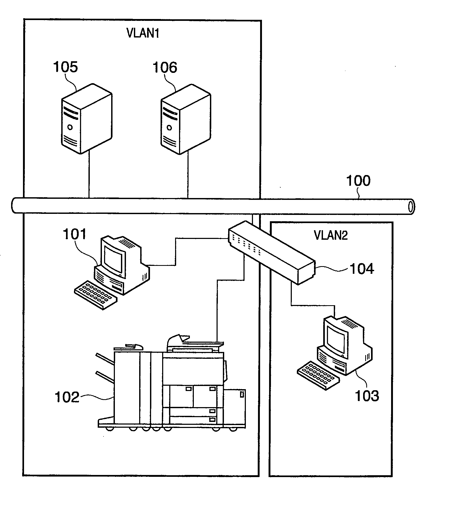
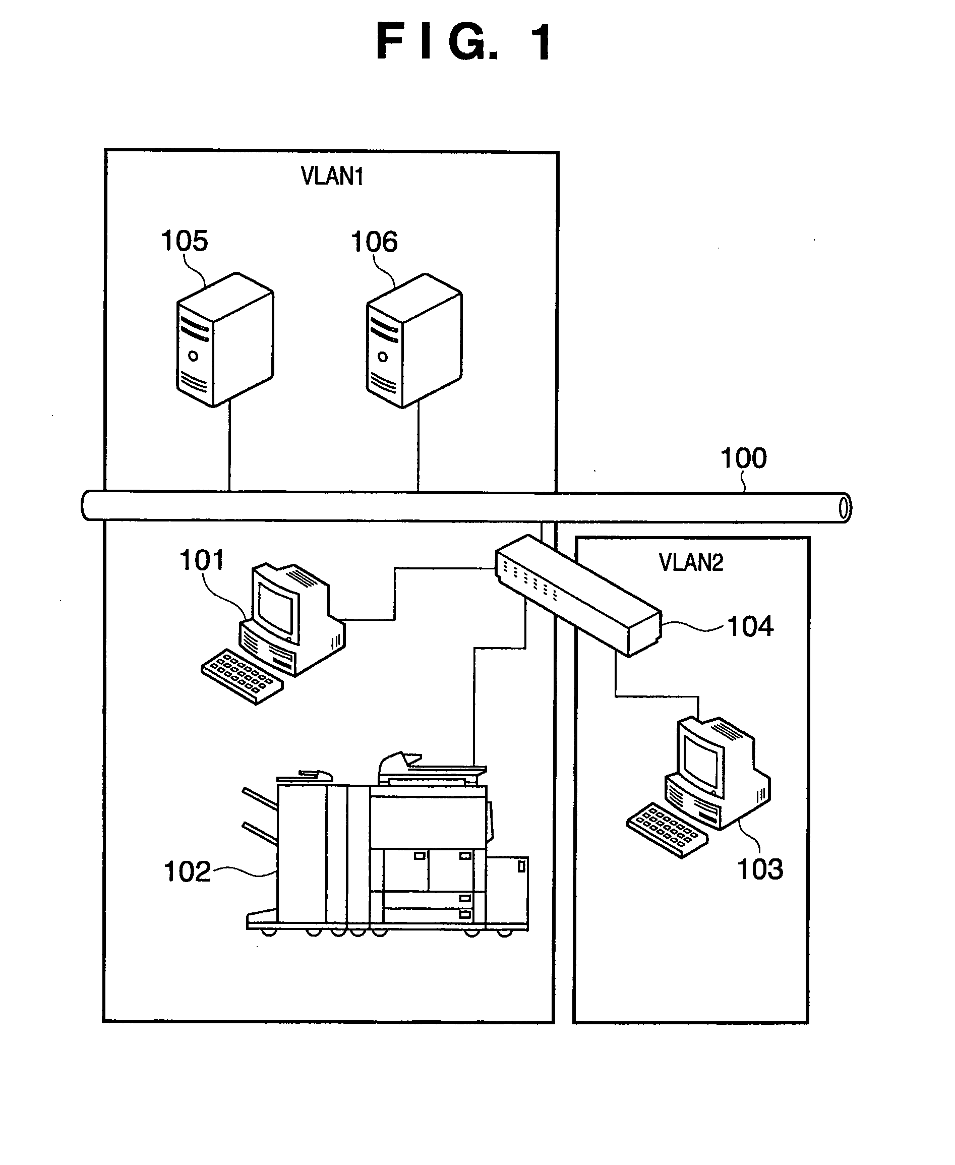
[0056]FIG. 1 is a view showing the configuration of a system according to this embodiment. As shown in FIG. 1, the system according to this embodiment comprises apparatuses 105 and 106 connected to a LAN 100, and apparatuses 101 to 103 connected to the LAN 100 via a switching apparatus 104. The apparatuses 101, 102, 105, and 106 belong (are connected) to VLAN 1, and the apparatus 103 belongs to VLAN 2. The switching apparatus 104 connects VLAN 1 and VLAN 2. The VLAN is a virtual network including a plurality of apparatuses permitted to be connected, and the details are as described above.

[0057]The apparatus 101 is a client terminal apparatus, the apparatus 102 is a multi-functional peripheral, the apparatus 105 is an authentication server, and the apparatus 106 is a DHCP server (network setting issuing server). As described above, these apparatuses are configured on VLAN 1 and can communicate data with each other by using VLAN 1.

[0058]The apparatus 104 is a switching apparatus, and ...

second embodiment

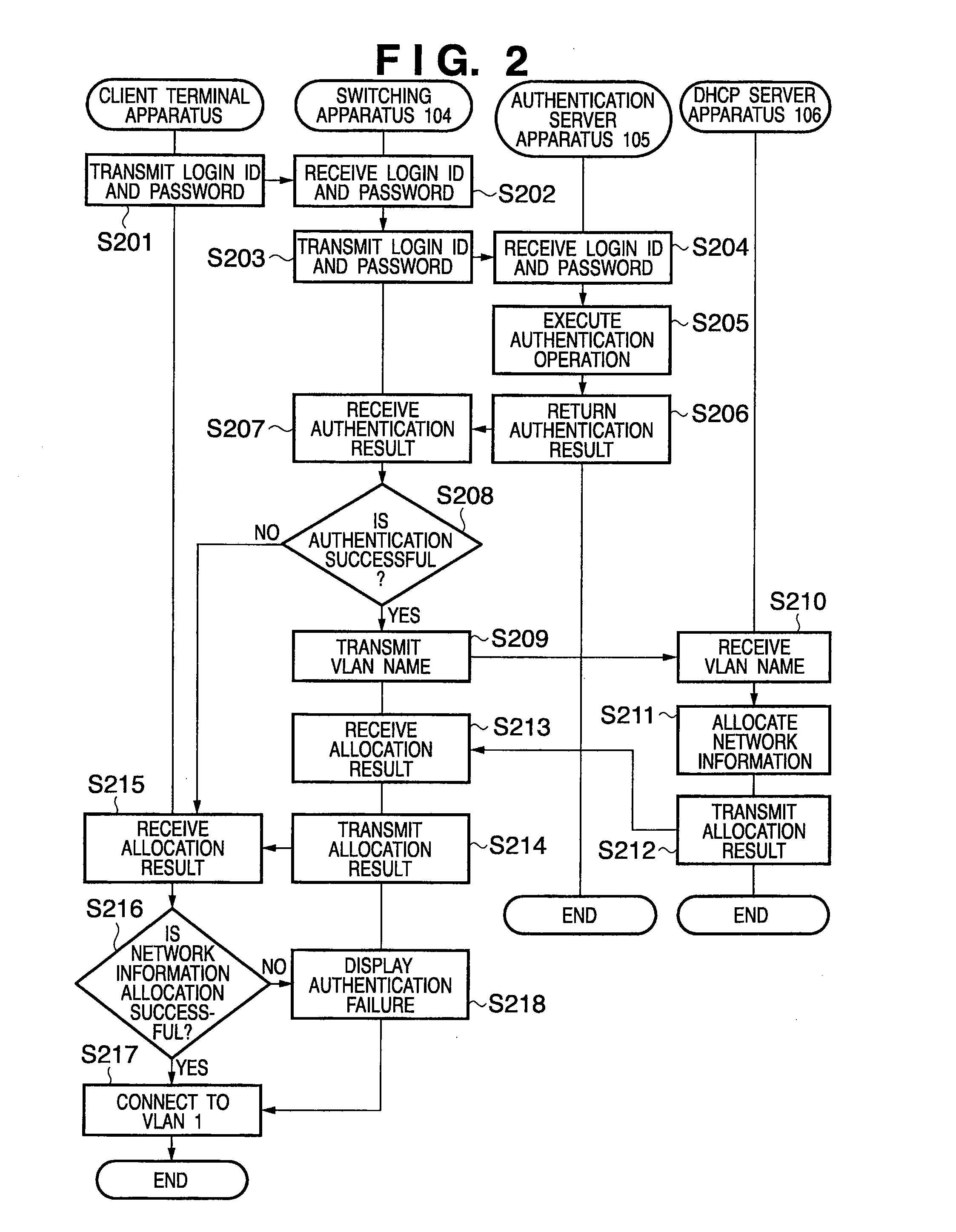
[0118]FIG. 11 is a flowchart of processing performed by a multi-functional peripheral 102 when a manager server apparatus 103 has transmitted a set of a login ID, password, IP address, and subnet mask in step S705 described above, and the multi-functional peripheral 102 has received the set. Note that programs and data for allowing a core unit 611 to execute the processing corresponding to the flowchart shown in FIG. 11 are stored in an internal memory (not shown) of the core unit 611. Therefore, the core unit 611 executes the processing by using the programs and data, thereby allowing the multi-functional peripheral 102 to execute each process explained below.

[0119]First, processes in steps S1101 to S1105 are respectively the same as those in steps S1001 to S1005 described above, so an explanation thereof will be omitted. Then, in step S1106, the core unit 611 compares a subnet based on the IP address and subnet mask transmitted from the manager server apparatus 103 with a subnet b...


PUM


Abstract

This invention provides a technique for safely and readily managing a network device. To achieve this object, an authentication server (105) performs an authentication process by using a set of a login ID and password transmitted from a manager server apparatus (103), and transmits the authentication result to a multi-functional peripheral (102). The authentication server (105) also specifies a VLAN name corresponding to this set, and transmits the VLAN name to a DHCP server (106). The DHCP server (106) determines connection setting information corresponding to the VLAN name, and transmits the determined connection setting information to the multi-functional peripheral (102). The multi-functional peripheral (102) connects to VLAN 2 by using the obtained connection setting information.

Description

BACKGROUND OF THE INVENTION[0001]1. Field of the Invention[0002]The present invention relates to an information processing technique in a virtual network.[0003]2. Description of the Related Art[0004]Recently, a VLAN (Virtual LAN) technique for setting a virtual group of network devices independently of a physical connection form is beginning to be established in a network (LAN) (e.g., Japanese Patent Laid-Open No. 2002-204247).[0005]The VLAN technique can set a group to which a network device belongs on the basis of the MAC address or IP address of the network device or information of the user using the network device. As a consequence, even when the network device is physically moved, the settings need not be changed. This saves the network manager the trouble of building a network, and makes the VLAN technique highly convenient for the network manager.[0006]On the other hand, even when a network device is connected to a network using the VLAN technique, this does not necessarily r...

Claims


Application Information

Patent Timeline
IPC IPC(8): H04L12/56H04L12/24H04L12/70
CPCH04L12/4675H04L41/08H04L41/082H04L63/083H04L45/00H04L63/0272H04L41/22H04L45/76H04L41/0895
Inventor IGARASHI, TOSHIAKI
Owner CANON KK
Learn More