
System and method for synchronizing serial digital interfaces over packet data networks

Inactive Publication Date: 2007-08-30
RADWIN
View PDF10 Cites 5 Cited by
  • Summary
  • Abstract
  • Description
  • Claims
  • Application Information

AI Technical Summary

Benefits of technology

[0017] Accordingly, it is a principal object of the present invention to provide a simple software and hardware solution to achieve precision. The software provides a simple means for clock accuracy and clock adjustment.
[0018] It is a further object of the present invention to provide a system which requires minimal hardware.
[0019] It is another object of the present invention to provide a system which is more economical.
[0025] The receiver side device also includes a clock recovery algorithm (CRA) in the form of a control loop responsible to calculate the difference between CIN and COUT based on the ability to measure a small deviation, such as 15 parts per billion (PPB) within seconds, based on the transmission using the CIND in the transmitter side device. The receiver side device also includes a CG responsible to generate the COUT based on internal reference CB and the CRA calculation, wherein CG resolution determines the COUT accuracy resolution of the 15 PPB. The receiver side device also includes an OLIU responsible to transmit the bit stream generated by the SER into the output serial line, such that small input clock deviations can be detected and adjusted for upon releasing the output bits into the output serial line.

Problems solved by technology

Without a jitter buffer to smooth the transmission, data can be lost, resulting in choppy audio signals.
Mitigating the effect of jitter on voice communication is one of the major challenges facing TDM / data network service vendors.
The bigger the buffer, the more delay, but if the buffer is too small, then voice quality can be compromised.
This solution is very accurate, but requires fairly expensive hardware in the form of the accurate clock.
Moreover, the accuracy of the clock recovery is limited in some network scenarios.

Method used


Image

  • System and method for synchronizing serial digital interfaces over packet data networks
  • System and method for synchronizing serial digital interfaces over packet data networks
  • System and method for synchronizing serial digital interfaces over packet data networks

Examples


Embodiment Construction

[0032] The principles and operation of a method and a system according to the present invention may be better understood with reference to the drawings and the accompanying description, it being understood that these drawings are given for illustrative purposes only and are not meant to be limiting.

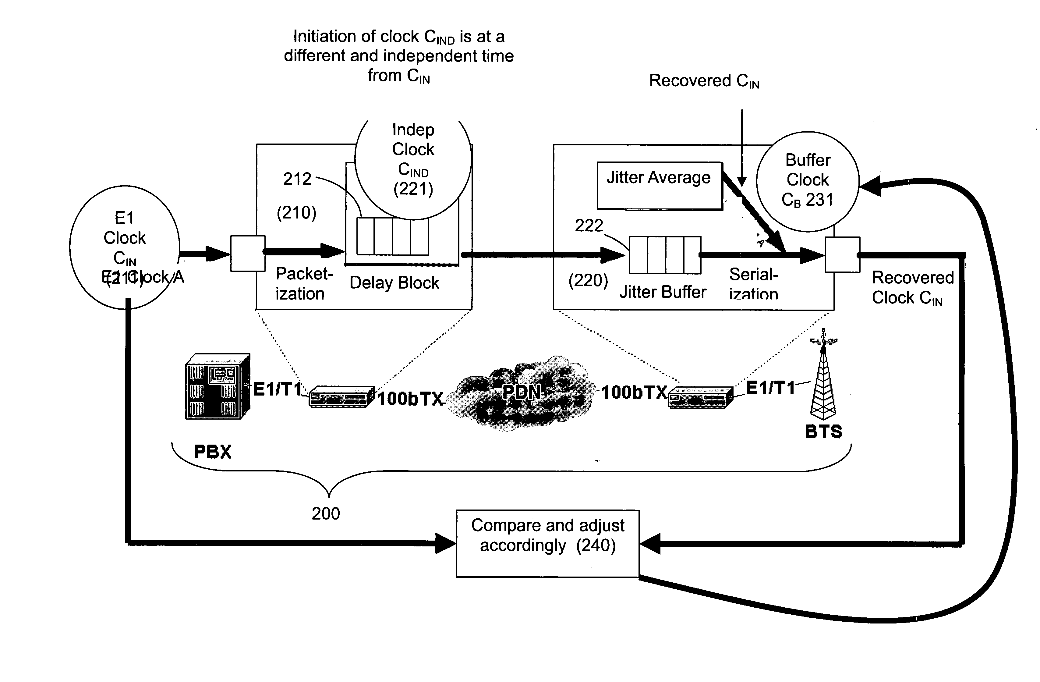
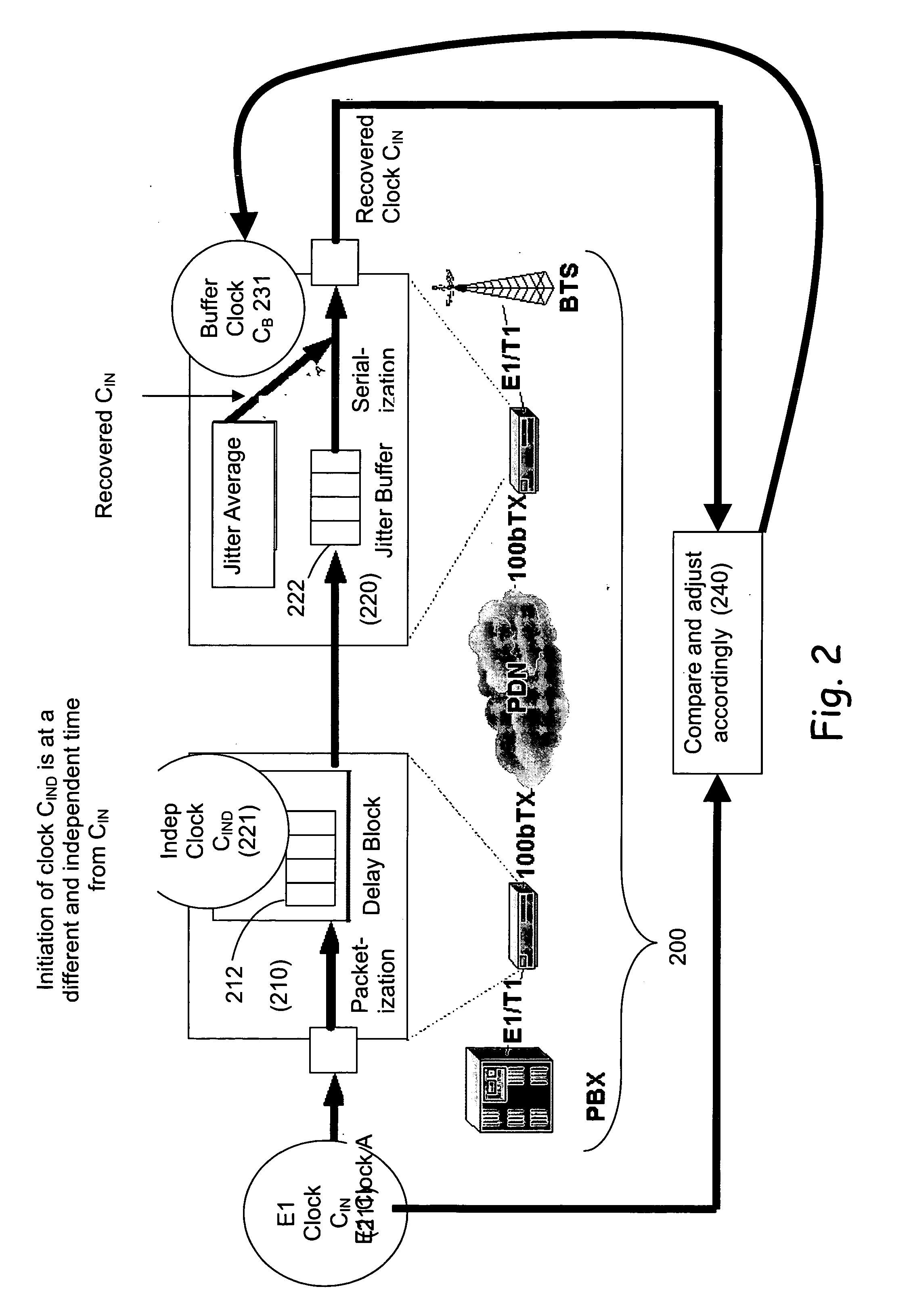
[0033]FIG. 2 is a general schematic block diagram illustrating synchronization method architecture, constructed in accordance with the principles of the present invention. A digitized E1 signal enters transmitter side device 210 of a TDMoIP / TDMoE system 200, and is transmitted according to an input clock CIN 211, where it first undergoes packetization into a delay block 212. The architecture of the present invention uses a sliding window that is based on a second, independent clock CIND 221, which runs on a different frequency from clock CIN 211, e.g., at ˜1000 parts / million (PPM) offset. Clock CIND 221 is used to delay the packets on transmitter side device 210 in delay block 212. On th...


PUM


Abstract

A system for synchronizing circuit interfaces for transmitting a serial bit stream in the form of data packets over a packet data network (PDN). The system includes a transmitter side device responsible to receive the data packets via a serial interface comprising data from an input serial line according to an input clock and output the data into a PDN. The system also includes a receiver side device responsible to receive the data packets from the PDN and to release the data packets into an output serial line, according to the difference between the input clock and an output clock (COUT), such that small input clock deviations can be detected and adjusted for upon releasing the output bits into the output serial line.

Description

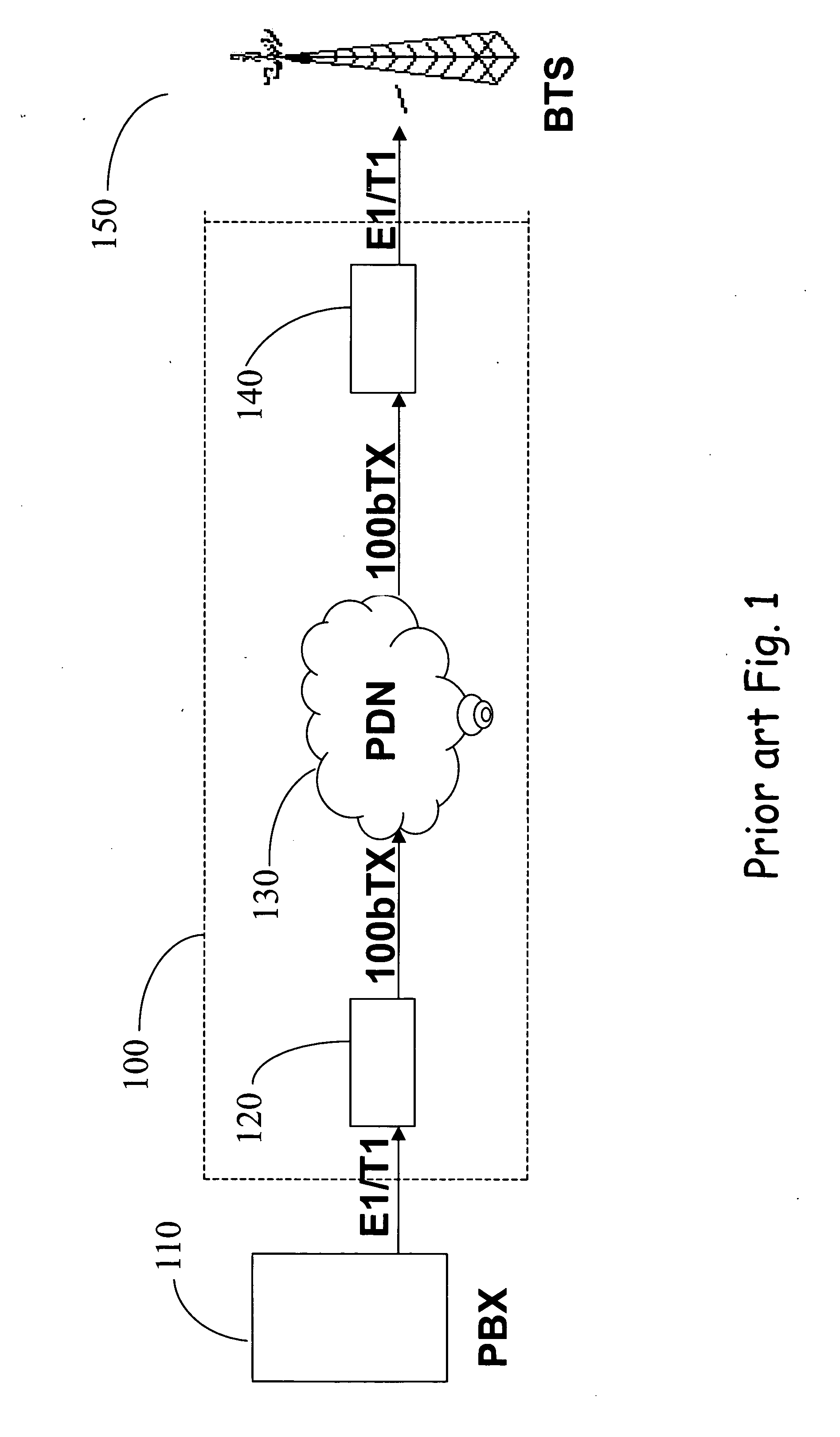
FIELD OF THE INVENTION [0001] The present invention relates to a system for packet data networks, and more particularly, to a method and devices for synchronizing serial data interfaces over packet data networks. BACKGROUND OF THE INVENTION [0002] With the growing implementation of fast packet data networks (PDN's), such as Local Area Networks (LAN's), Wireless Local Area Networks (WLAN's) and Metropolitan Area Networks (MAN's), there is a demand to transport circuit switching services over these PDN's. The circuit switch service requires synchronizing the two end clocks, as well as the passing of the data (bit stream). The requirement for synchronization is defined in G.823, G.824, G.811 and G.812 standards. [0003] There is a demand to transfer legacy services, such as Time Division Multiplexing (TDM), over the new high-speed packet switching networks. [0004] A jitter buffer is a hardware device or software process that eliminates jitter caused by transmission delays over a data ne...

Claims


Application Information

Patent Timeline
IPC IPC(8): H04L12/56
CPCH04J3/0632
Inventor KAPON, RON
Owner RADWIN
Learn More