Analysis method for sound or vibration and analyzing apparatus for sound or vibration

a technology of analysis apparatus and analysis method, applied in the direction of electrical transducers, structural/machine measurement, instruments, etc., can solve the problems of insufficient reduction effect of sound or vibration, and difficulty in correctly identifying the generation source of sound or vibration at the evaluation poin

Inactive Publication Date: 2007-08-30
JTEKT CORP +1
View PDF6 Cites 12 Cited by
  • Summary
  • Abstract
  • Description
  • Claims
  • Application Information

AI Technical Summary

Benefits of technology

[0006] Nevertheless, these conventional analysis methods do not utilize time information, and hence have a problem that when sound or vibration in the same or near frequency range is detected at a plurality of candidate points, a generation source of the sound or vibration that appears at the evaluation point is difficult to be identified correctly. Thus, even when a countermeasure is taken at any one of the plurality of candidate points, the taken countermeasure could be at a candidate point other than the actual sound source or vibration source, so that the reduction effect for sound or vibration could be insufficient at the evaluation point. In contrast, if countermeasures were taken at all of the plurality of candidate points, this would disadvantageously cause excessive countermeasures even at unnecessary candidate points.

Problems solved by technology

Nevertheless, these conventional analysis methods do not utilize time information, and hence have a problem that when sound or vibration in the same or near frequency range is detected at a plurality of candidate points, a generation source of the sound or vibration that appears at the evaluation point is difficult to be identified correctly.
Thus, even when a countermeasure is taken at any one of the plurality of candidate points, the taken countermeasure could be at a candidate point other than the actual sound source or vibration source, so that the reduction effect for sound or vibration could be insufficient at the evaluation point.
In contrast, if countermeasures were taken at all of the plurality of candidate points, this would disadvantageously cause excessive countermeasures even at unnecessary candidate points.

Method used


Image

  • Analysis method for sound or vibration and analyzing apparatus for sound or vibration
  • Analysis method for sound or vibration and analyzing apparatus for sound or vibration
  • Analysis method for sound or vibration and analyzing apparatus for sound or vibration

Examples


Embodiment Construction

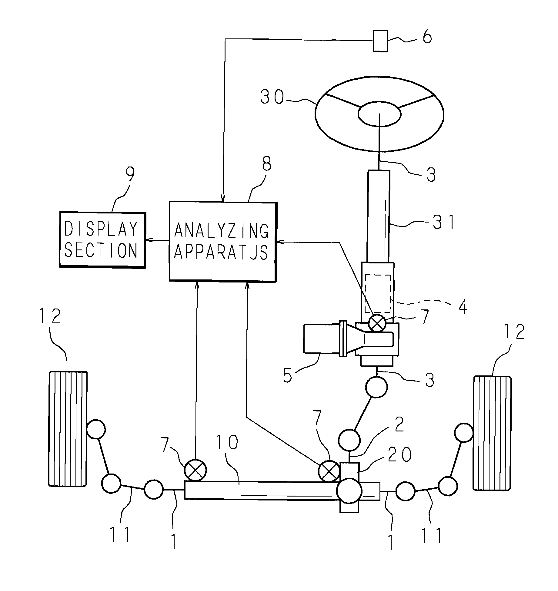
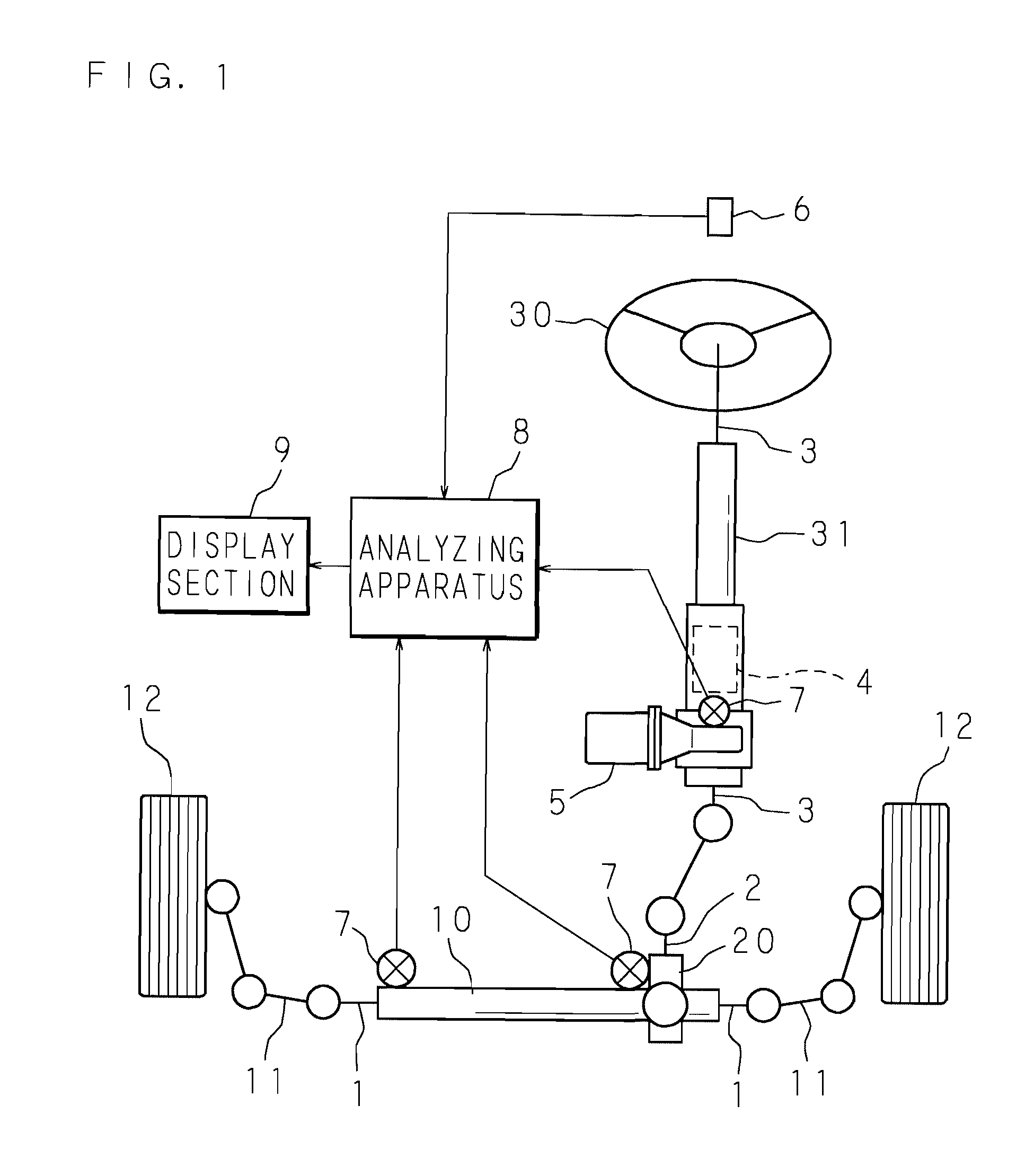
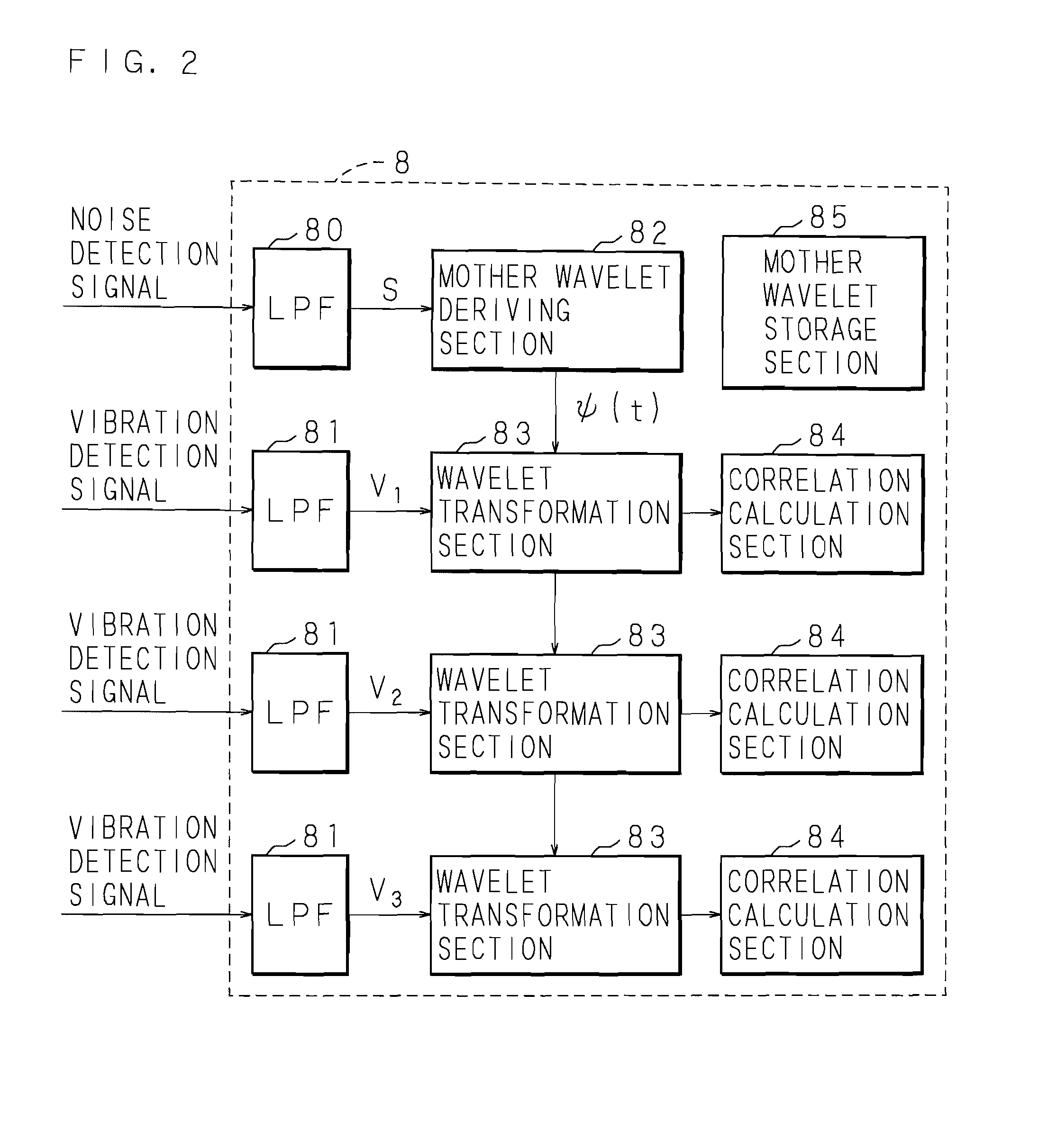
[0019] The present invention is described below in detail with reference to the drawings showing an embodiment. FIG. 1 is an explanatory view showing a state of implementation of an analysis method for sound or vibration according to the present invention. This figure shows a state of implementation of an analysis method for identifying which of the vibration sources present in various sections of an electric power steering device provided in an automobile causes the noise generated inside the car cabin.

[0020] The electric power steering device shown in FIG. 1 has a steering mechanism of rack and pinion type provided with a rack shaft 1 supported in a movable manner in the axial length direction in the inside of a rack housing 10 that extends in the right and left directions of a car body and with a pinion shaft 2 supported in a rotatable manner in the inside of a pinion housing 20 that intersects with the middle of the rack housing 10.

[0021] The two ends of the rack shaft 1 that ...


PUM


Abstract

A detection signal of sound or vibration detected at an evaluation point is filtered so that an evaluation waveform signal is extracted. Then, a mother wavelet is derived using this. On the other hand, each of detection signals of sound or vibration detected at a plurality of candidate points is filtered so that each candidate waveform signal is extracted. These candidate waveform signals are processed by wavelet transformation using the derived mother wavelet. Then, on the basis of the result, instantaneous correlation is calculated between each candidate waveform signal and the mother wavelet. Then, on the basis of mutual comparison of the calculated instantaneous correlation, a generation source of the sound or vibration that appears at the evaluation point is identified.

Description

CROSS-REFERENCE TO RELATED APPLICATIONS [0001] This Nonprovisional application claims priority under 35 U.S.C. §119(a) on Patent Application No. 2006-25155 filed in Japan on Feb. 1, 2006, the entire contents of which are hereby incorporated by reference. BACKGROUND OF THE INVENTION [0002] The present invention relates to an analysis method and an analyzing apparatus for identifying which of a plurality of sound sources or vibration sources located in a target space or its periphery causes noise or vibration at an evaluation point within the target space. [0003] Identification of a generation source of noise or vibration that appears at an evaluation point within a space is an important issue in various fields of industry. For example, reduction in the internal noise of a car cabin, especially in the noise heard by passengers in a car cabin, is important in the improvement of the passengers' comfortableness. For this purpose, a sound source or a vibration source of the target noise n...

Claims


Application Information

Patent Timeline
Patent Type & Authority Applications(United States)
IPC IPC(8): H04B15/00H04R29/00G01M99/00
CPCG01H3/125
Inventor ISHII, HIDEAKIUEMURA, HIROSHIZHANG, ZHONG
Owner JTEKT CORP
Why Eureka
Try Eureka