Roller Connecting and Retaining Device

a technology of connecting and retaining device, which is applied in the direction of linear bearings, rotary bearings, shafts and bearings, etc., can solve the problems of long production time, still some problems to be solved, and consumers still need uninterrupted technology improvement, etc., and achieve the effect of fast mass production

Active Publication Date: 2007-08-30
HIWIN TECH
View PDF4 Cites 4 Cited by
  • Summary
  • Abstract
  • Description
  • Claims
  • Application Information

AI Technical Summary

Benefits of technology

[0020] The primary objective of the present invention is to provide a roller connecting and retaining device that is suitable for integral formation and fast mass production.

Problems solved by technology

Although the technology for linear transmission element is developing fast, consumers still need the technology to be improved uninterruptedly.
Therefore, there are still some problems to be solved.
When the chain 12 is comparatively long, the number of to-be-implanted rollers 10 will be relative large, the production time will be long and production complexity will be increased, and the resultant technical cost will be relatively high.
2, the spacer portion 11 of the chain 12 is formed directly between the rollers 10 by using the rollers 10 as mold core, it must apply release agent between the spacer portion 11 and the rollers 10 prior to the formation of the spacer portion 11, this also makes the production process more complicated and increases the production cost.
Furthermore, the size of the mold has to change according to different sizes (when the size is comparatively long, the mold will become large), the production complexity will be increased, and the resultant production cost will be relatively high.
2, the spacer portion 13 is formed directly between the rollers 10 by using the rollers 10 as mold core, it must apply release agent between the spacer portion 13 and the rollers 10 prior to the formation of the spacer portion 13, this also makes the production process more complicated and increases the production cost.
Since making such a guiding groove is not easy, the production cost of this second conventional embodiment will still be high, moreover, the protruding connecting portion 131 may interfere with the rolling motion of the rollers.
Since the rollers 10 are only subjected to a retaining force from a single side, the spacer portion 16 will be likely to sway with the cooperation of the slant supporting portions 14, this only will cause the operation to be unstable.
It is understood from the conventional products described above that the roller system of the linear mechanism is still unable to maintain a stable operation.

Method used


Image

  • Roller Connecting and Retaining Device
  • Roller Connecting and Retaining Device
  • Roller Connecting and Retaining Device

Examples


Embodiment Construction

[0034] The foregoing, and additional objects, features and advantages of the present invention will become apparent from the following detailed description of preferred embodiment thereof, taken in conjunction with the accompanying FIGS. 4 and 6.

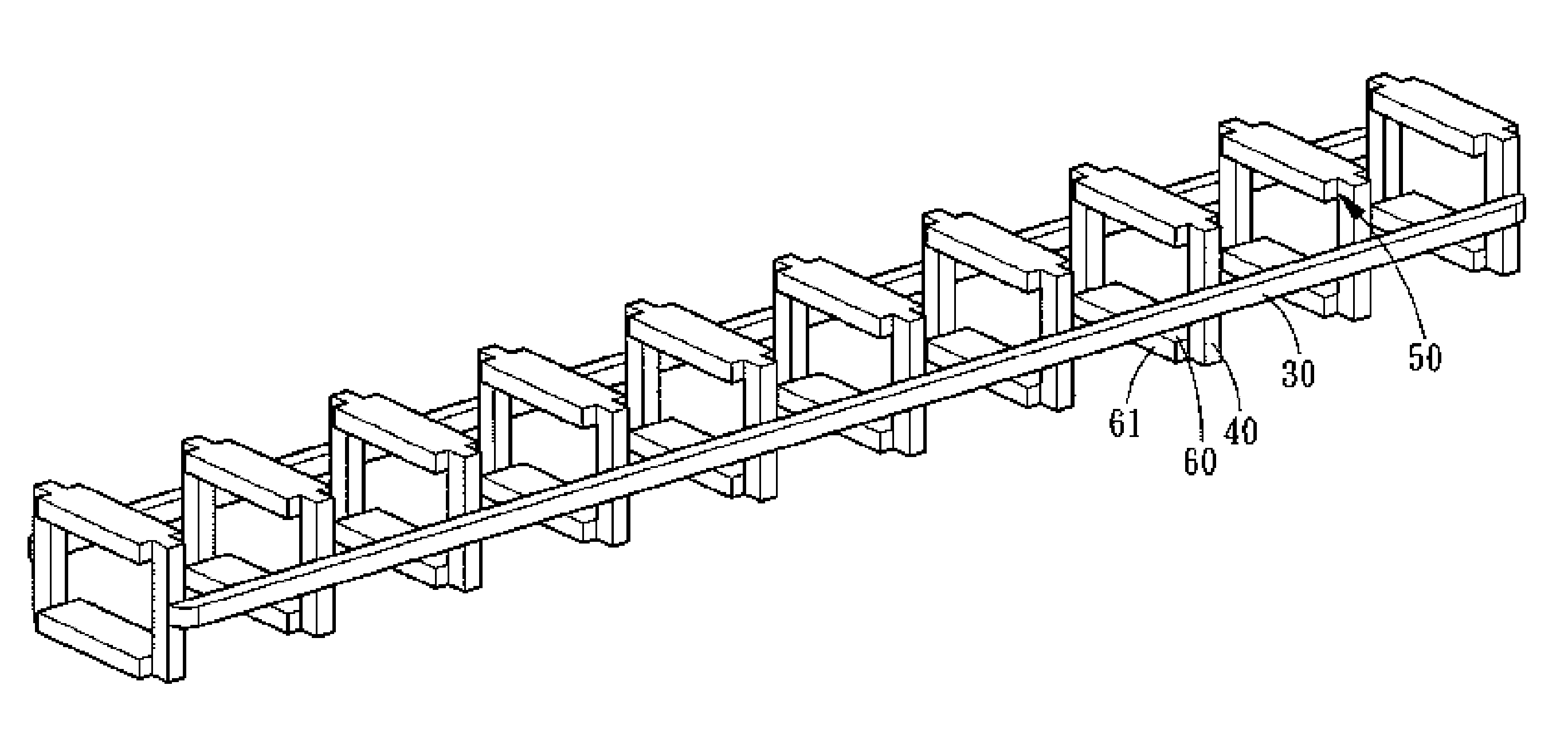
[0035] The roller connecting and retaining device in accordance with the present invention is mounted on a plurality of rollers 20 and circulates in the roller rolling passage of the linear system. The rolling connecting and retaining device comprises two connecting portions 30, a plurality of retaining portions 40, and a plurality of spacer portions 60.

[0036] The connecting portions 30 are mounted at both end surfaces 21 of the rollers 20 and approximately located an equal distance from the two contacting portions 221 of the rolling surfaces 22 of the rollers 20. In fact, it will be ok if the connecting portion of the present invention is maintained between the two contacting portions 221 of the rolling surfaces 22 of the rollers 20.

[003...


PUM


Abstract

A roller connecting and retaining device comprises two connecting portions, a plurality of retaining portions and spacer portions. The retaining portions are oppositely arranged in pairs and connected vertically to the connecting portions. The spacer portions are connected between the upper end and the lower end of the paired opposite retaining portions. Two contacting edges are formed at both sides of the respective spacer portions and have a linear contact with the rolling surface of the rollers, and the contacting edges of the opposite spacer portions are located correspondingly to the axial center of the rollers and are arranged at both sides of the inactive contact surface of the rollers. A mold-releasing concave is formed in each conjunction between the spacer portion and the retaining portion. Such design facilitates injection molding process, mold opening, and mass production. The contacting edge of the opposite spacer portions can prevent the problems of the rollers during rolling motion, such as slant position, friction, impact and skip.

Description

BACKGROUND OF THE INVENTION [0001] 1. Field of the Invention [0002] The present invention relates to a connecting and retaining device for a linear mechanism using rollers as rolling elements, wherein the special design of the spacer portion is suitable for integral formation and fast mass production, and can prevent skew position, friction and impact of the rollers, ensuring a stable transmission. [0003] 2. Description of the Prior Art [0004] Since linear transmission products are being applied more and more widely in the modern industry, various linear transmission mechanisms have widely come into human life, manufacturing factory and high science and technology instruments, such as linear guideway, ball screw, and the like. Particularly in a large-scale precision mechanism are usually installed various large and small ball screws or linear guideway systems. Although the technology for linear transmission element is developing fast, consumers still need the technology to be improv...

Claims


Application Information

Patent Timeline
Patent Type & Authority Applications(United States)
IPC IPC(8): F16C19/00
CPCF16C33/506F16C29/06
Inventor WU, CHUN-LIANGCHEN, EN-CHIEH
Owner HIWIN TECH
Why Eureka
Try Eureka