Impeller Of Multiblade Fan And Multiblade Fan Having The Same

a technology of multi-blade fans and components, which is applied in the direction of marine propulsion, liquid fuel engines, vessels, etc., can solve the problems of increased noise, deterioration of blowing performance, and increased nois

Active Publication Date: 2007-08-30
DAIKIN IND LTD
View PDF11 Cites 15 Cited by
  • Summary
  • Abstract
  • Description
  • Claims
  • Application Information

AI Technical Summary

Benefits of technology

[0020] In this multiblade fan, it becomes possible to allow the swirling flow to flow smoothly in the space between the inn

Problems solved by technology

This swirling flow X flows into the space on the inner peripheral side of the impeller 13 and merges with the suction main flow W sucked in from the suction opening 11a of the casing 11, but when the vector of the suction main flow W and the vector of the flow of the swirling flow X

Method used


Image

  • Impeller Of Multiblade Fan And Multiblade Fan Having The Same
  • Impeller Of Multiblade Fan And Multiblade Fan Having The Same
  • Impeller Of Multiblade Fan And Multiblade Fan Having The Same

Examples


first embodiment

(1) Configuration of Multiblade Fan

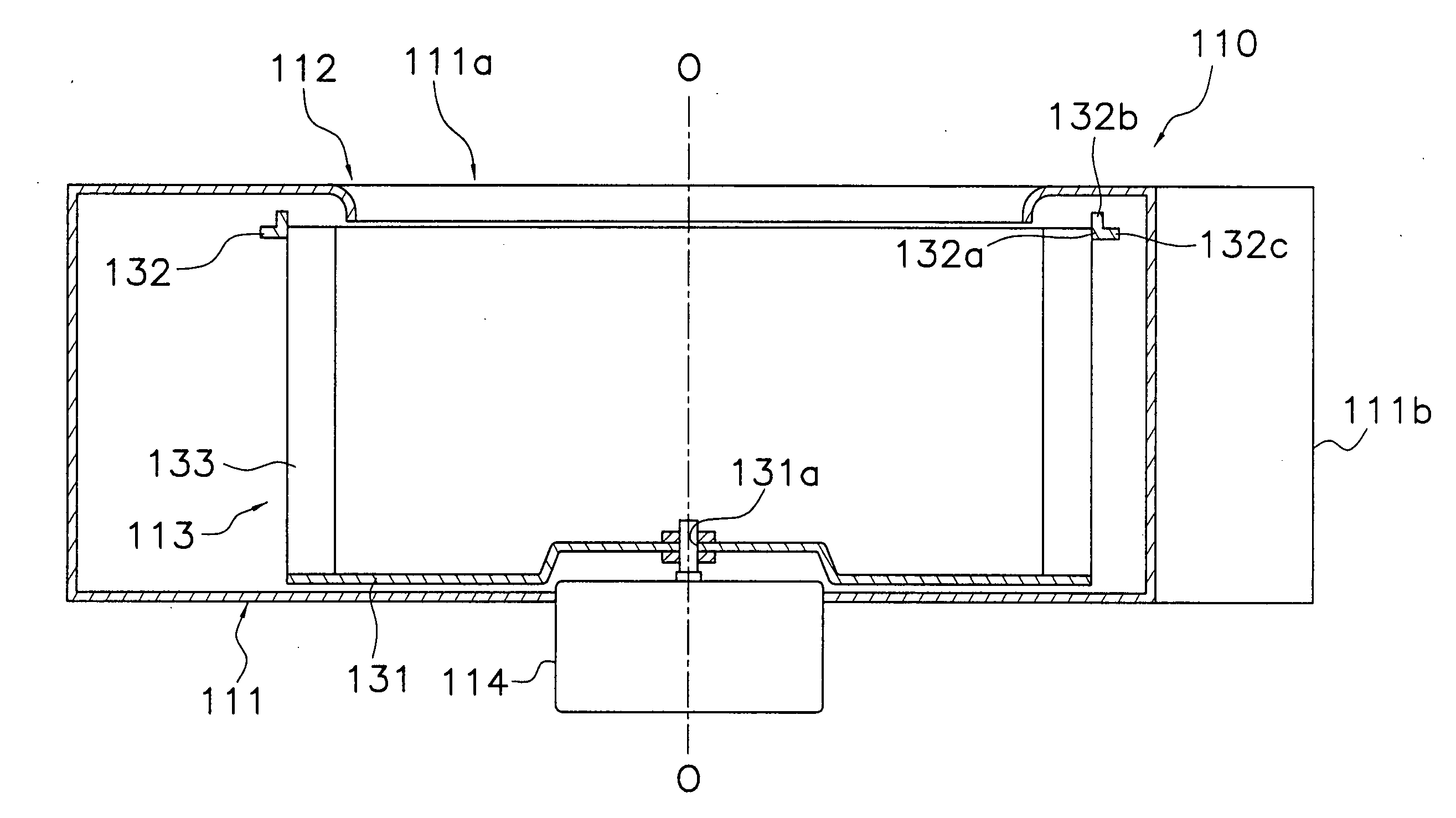
[0049]FIG. 3 and FIG. 4 show a multiblade fan 110 pertaining to a first embodiment of the present invention. Here, FIG. 3 shows a side view of the multiblade fan 110 pertaining to the first embodiment of the present invention. FIG. 4 is an enlarged view of FIG. 3 and is a view showing the vicinity of a side plate 132 of an impeller 113 of the multiblade fan 110.

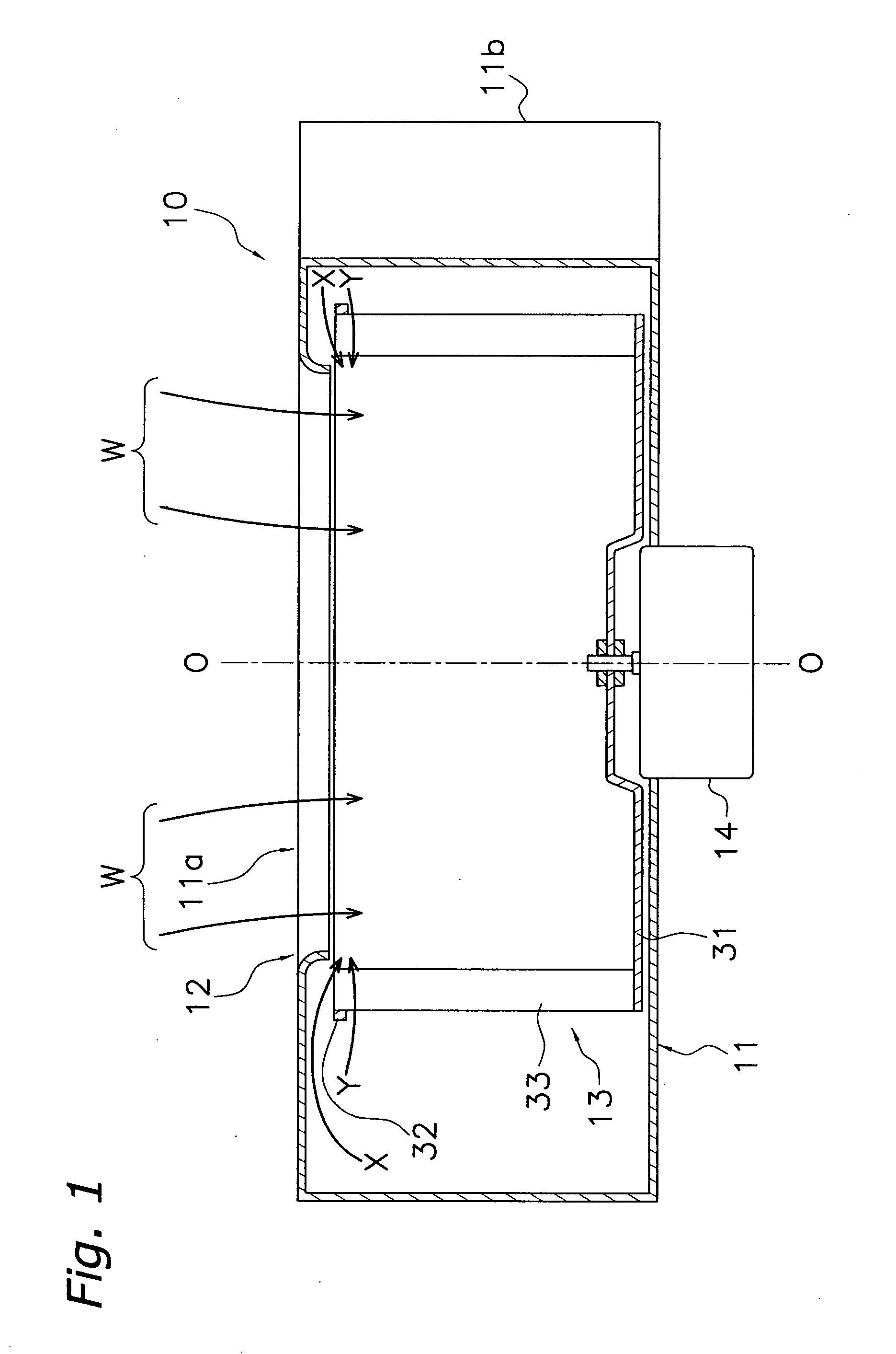
[0050] Similar to the conventional multiblade fan 10 (see FIG. 1 and FIG. 2), the multiblade fan 110 is a single suction type multiblade fan and is configured by an impeller 113, a casing 111 that houses the impeller 113, and a motor 114 for driving the impeller 113 to rotate and the like. Here, O-O in FIG. 3 is the axial line of rotation of the impeller 113 and the motor 114.

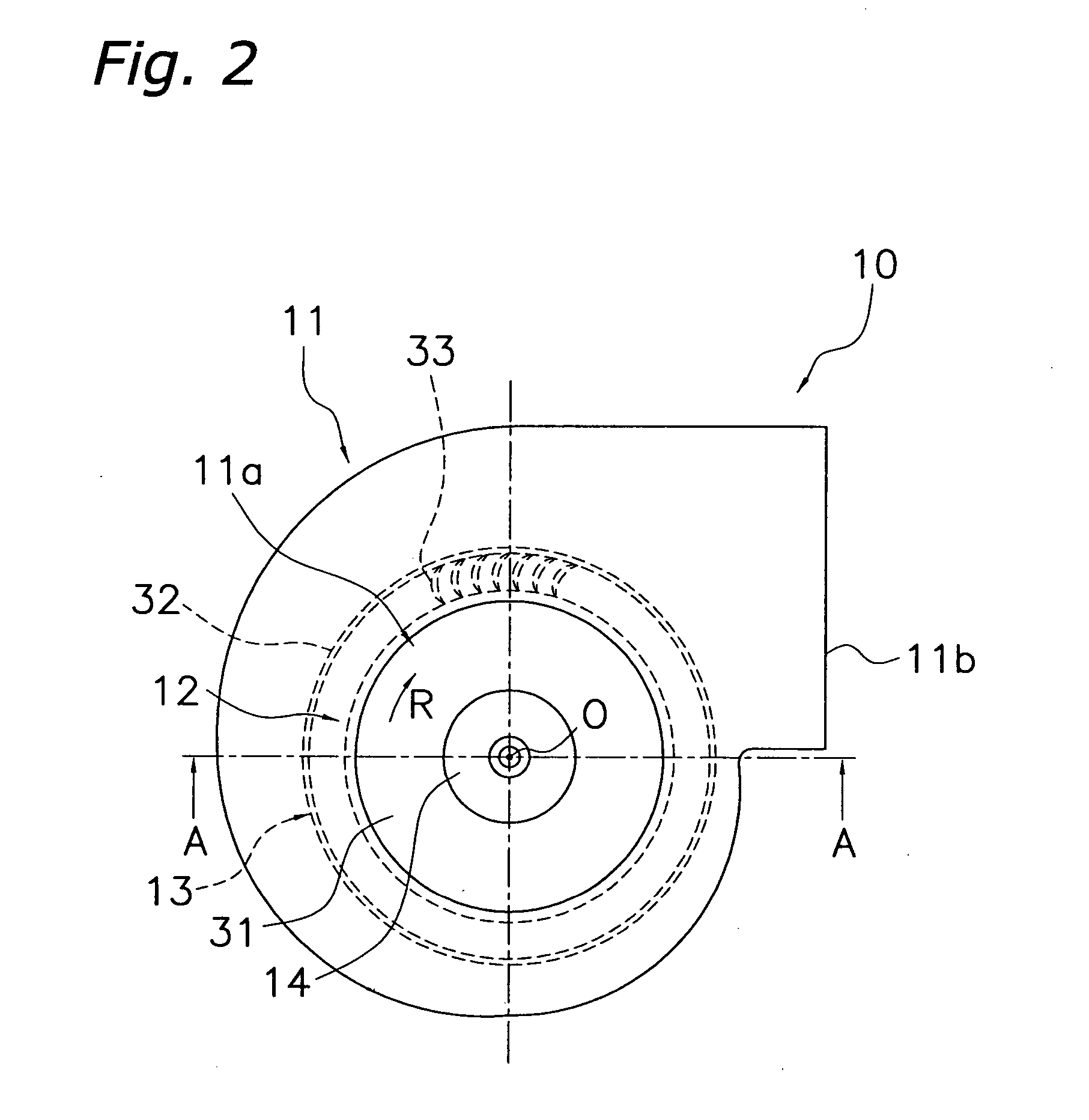
[0051] Similar to the conventional multiblade fan 10, the casing 111 is a casing with a scroll shape when seen in plan view (see FIG. 2) and includes a suction opening 111a that sucks in gas from one side in the rot...

second embodiment

(1) Configuration of Multiblade Fan

[0074]FIG. 9 shows a multiblade fan 210 pertaining to a second embodiment of the present invention. Here, FIG. 9 shows a side view of the multiblade fan 210 pertaining to the second embodiment of the present invention.

[0075] The multiblade fan 210 is an example where the present invention is applied to a double suction type multiblade fan and is configured by an impeller 213, a casing 211 that houses the impeller 213, a motor 214 for driving the impeller 213 to rotate, and the like. Here, O-O in FIG. 9 is the axial line of rotation of the impeller 213 and the motor 214.

[0076] Similar to the conventional multiblade fan 10, the casing 211 is a casing with a scroll shape when seen in plan view (see FIG. 2), but in contrast to the single suction type multiblade fan 110, it includes suction openings 211a and 211 c that suck in gas from both sides in the rotational axis O direction and a blowout opening 211b that blows out gas in a direction intersec...

first modification

(4) First Modification

[0093] In the impeller 213 of the above-described multiblade fan 210, the radial-direction outer peripheral edge surfaces of the axially extending portions 232b and 234b and the opposite-main plate side surfaces of the radially extending portions 232c and 234c of the side plates 232 and 234 are connected such that they are substantially orthogonal to each other, but radial-direction outer peripheral edge surfaces of axially extending portions 242b and 244b and opposite-main plate side surfaces of radially extending portions 242c and 244c of side plates 232 and 234 may also be smoothly connected as in an impeller 243 shown in FIG. 13. Thus, the swirling flow (see the swirling flow X1 of FIG. 4) flowing from the outer peripheral side to the inner peripheral side of the impeller 243 can be smoothly guided to the opposite-main plate side.


PUM


Abstract

To provide an impeller of a multiblade fan capable of reducing noise and improving blowing performance and a multiblade fan having the same. An impeller (113) of a multiblade fan (110) includes a discoid main plate (131) that rotates about a rotational axis, plural blades (133), and a side plate (132). The plural blades (133) are disposed annularly about the rotational axis on one side of the main plate (131), with one end of each of the blades being fixed to an outer peripheral portion of the main plate (131). The side plate (132) includes an annular side plate body portion (132a) that joins outer peripheral edges of the other ends of the plural blades (133) to each other, an axially extending portion (132b) that extends from the opposite-main plate side end of the side plate body portion (132a) further toward the opposite-main plate side in the rotational axis direction than the opposite-main plate side ends of the blades (133), and a radially extending portion (132c) that extends from the outer peripheral end of the side plate body portion (132a) further toward the outer peripheral side than the radial-direction outer peripheral end of the axially extending portion (132b).

Description

TECHNICAL FIELD [0001] The present invention relates to an impeller of a multiblade fan and to a multiblade fan having the same, and in particular to an impeller of a multiblade fan where end portions of plural blades extending from a main plate are connected to each other by an annular side plate and to a multiblade fan having the same. BACKGROUND ART [0002] In air purifiers and air conditioners and the like, a multiblade fan is used in order to perform blowing. As a conventional example, FIG. 1 and FIG. 2 show an example of a single suction type multiblade fan. Here, FIG. 1 shows a side view (specifically, an A-A cross-sectional view of FIG. 2) of the conventional single suction type multiblade fan, and FIG. 2 shows a plan view of the conventional single suction type multiblade fan. [0003] A multiblade fan 10 is configured by an impeller 13, a casing 11 that houses the impeller 13, a motor 14 for driving the impeller 13 to rotate and the like. Here, axis O-O in FIG. 1 and FIG. 2 i...

Claims


Application Information

Patent Timeline
IPC IPC(8): F04D29/44
CPCF04D29/162F04D29/667F04D29/441F04D29/281
Inventor HIGASHIDA, MASAHITO
Owner DAIKIN IND LTD
Why Eureka
Try Eureka