Process for monitoring the setting of the coolant nozzle of a grinding machine

a technology for grinding machines and coolant nozzles, which is applied in the direction of grinding machines, grinding machine components, manufacturing tools, etc., can solve the problems of inadequate cooling of grinding machines, fire to the machine, and inferior surface quality or other deficiencies, and achieve the effect of deficient setting of the coolant nozzles

Inactive Publication Date: 2007-08-30
REISHAUER
View PDF3 Cites 16 Cited by
  • Summary
  • Abstract
  • Description
  • Claims
  • Application Information

AI Technical Summary

Benefits of technology

[0006]An object of the present invention, therefore, is to propose a process for monitoring the correct position of the coolant nozzle of a grinding machine, in particular of a machine for grinding the tooth flanks of workpieces with prema

Problems solved by technology

A deficient setting of the coolant nozzle results in the process being inadequately cooled and, due e.g. to overheating, the workpiece having an inferior surface quality or other deficiencies, making it unusable.
Moreover due to too high temperatures of the contact surface between grinding wheel and workpiece, or to flying sparks, a deflagration of the coolant liquid and air mixture can be triggered in the machine working area, which can set fire to the machine.
The disadvantage of this solution is that the confirmation of the setting of the

Method used


Image

  • Process for monitoring the setting of the coolant nozzle of a grinding machine
  • Process for monitoring the setting of the coolant nozzle of a grinding machine
  • Process for monitoring the setting of the coolant nozzle of a grinding machine

Examples


Embodiment Construction

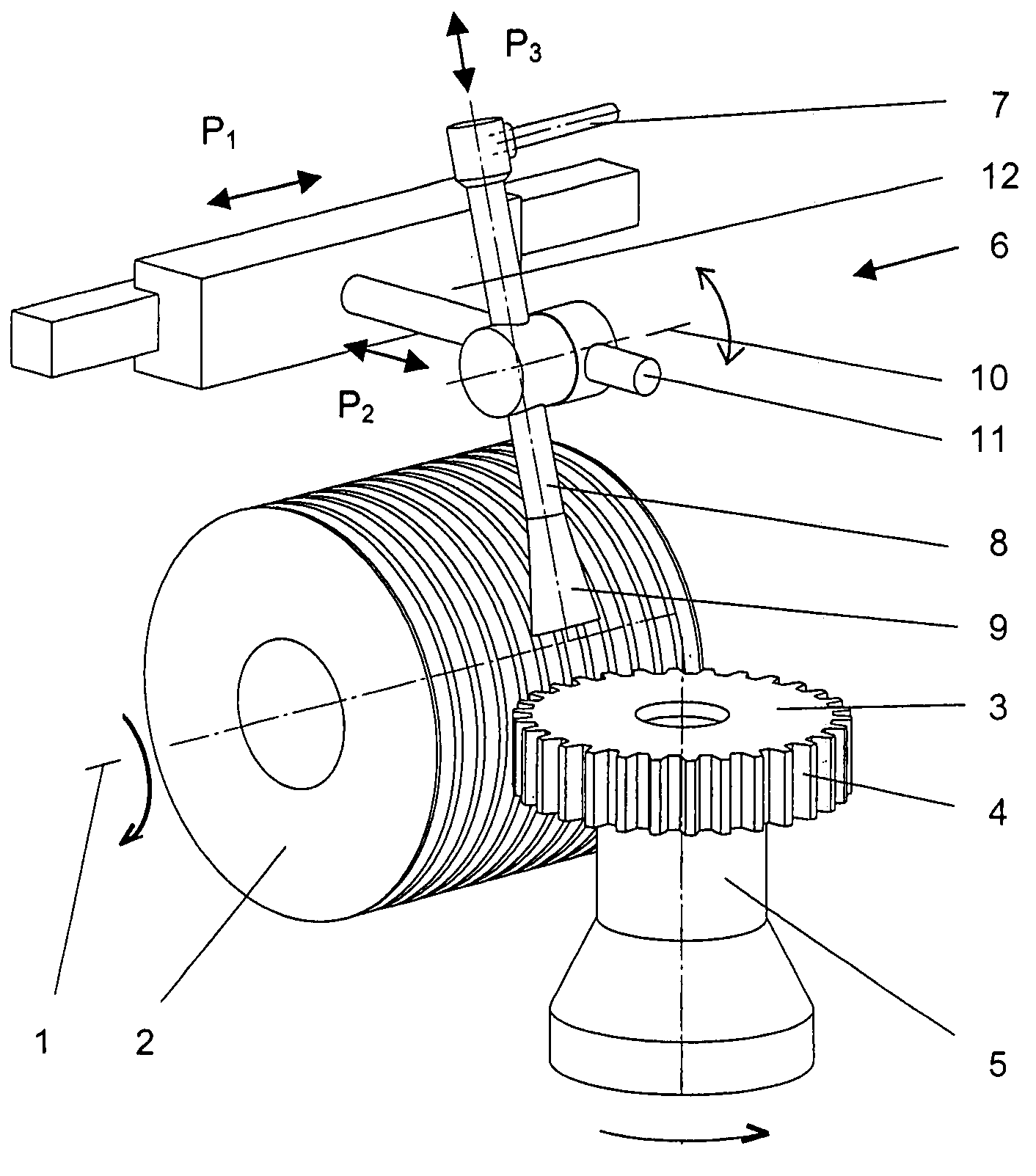
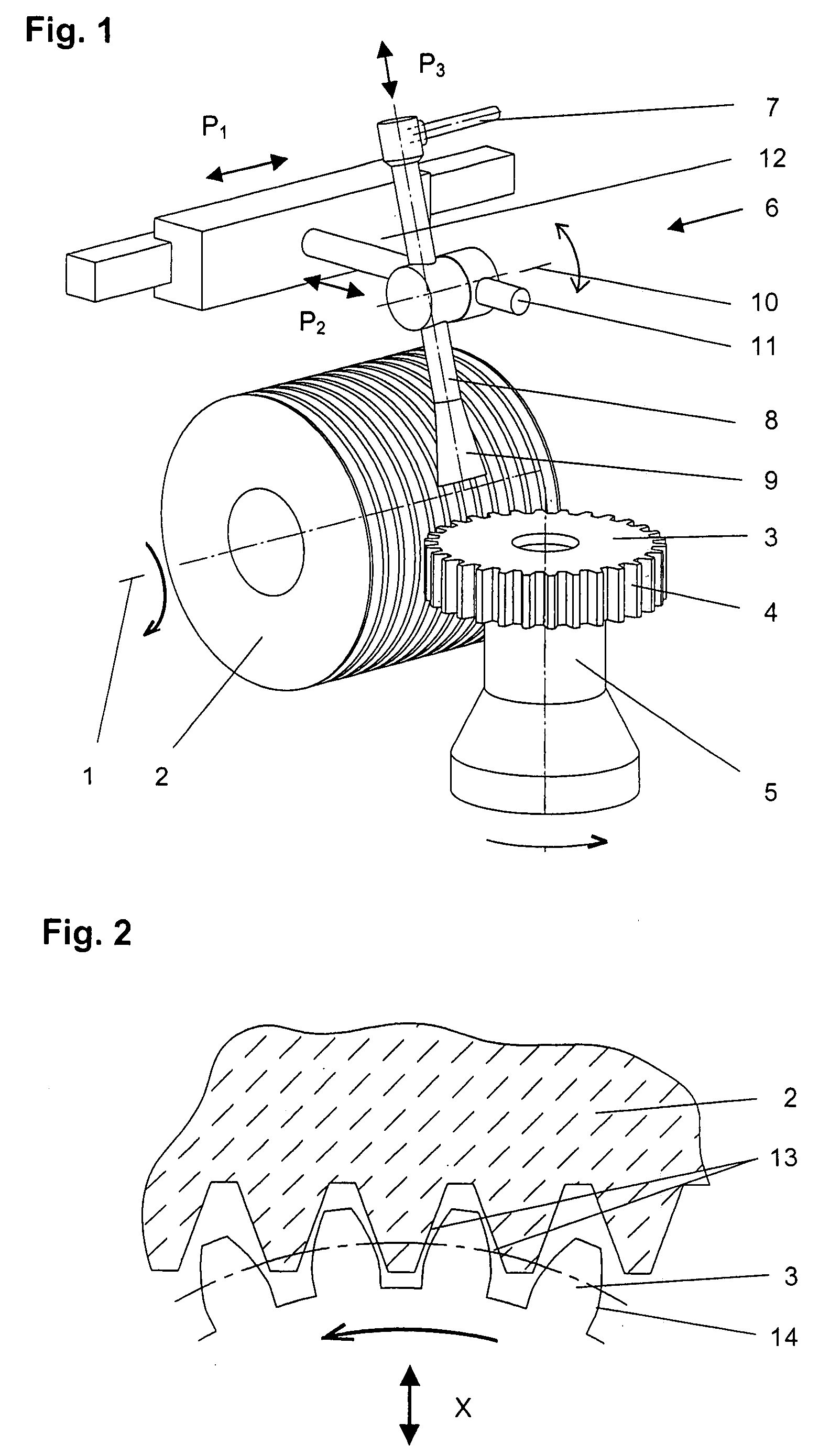
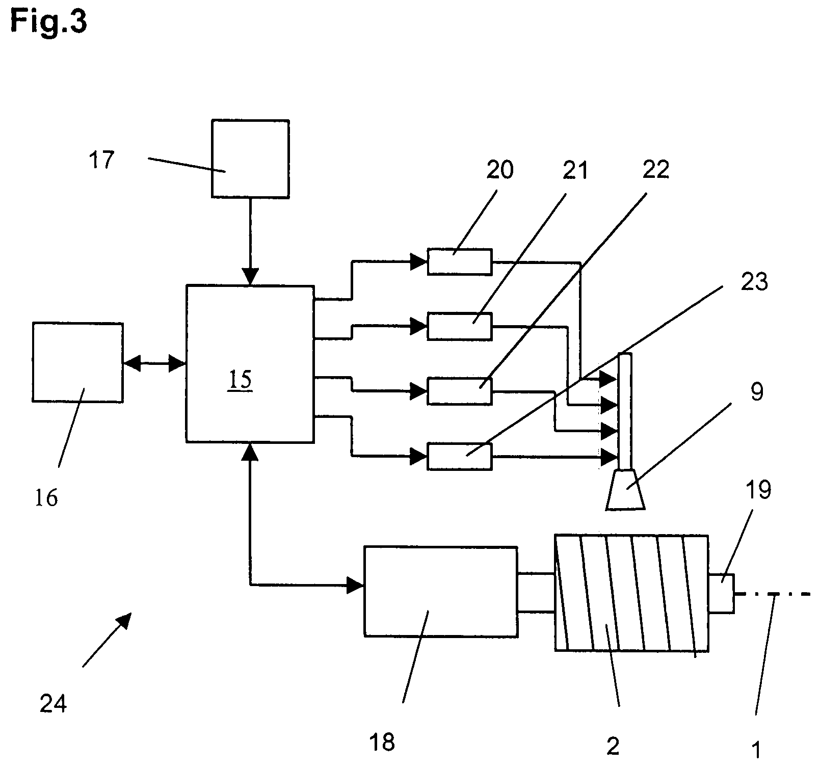
[0024]The invention is described in detail using the example of a grinding machine (24 in FIG. 3) for the continuous generative grinding of the flanks of gears with premachined teeth. FIG. 1 shows a grinding worm 2 located for rotation about a grinding spindle axis 1 in a grinding spindle (19 in FIG. 3) on the grinding machine 24, the said grinding worm 2 being driven by a grinding spindle drive (18 in FIG. 3) not shown in FIG. 1. The workpiece (gear) 3 with external teeth 4 is set up on a work fixture 5, which is connected to the machine for driven rotation and displaceable in the infeed direction X relative to the grinding worm 2.

[0025]The coolant supply 6 comprises a coolant hose 7, a supply tube 8 and a coolant nozzle 9 connected to the latter. The supply tube 8 is displaceable in its longitudinal direction (coolant nozzle infeed direction) P3, swivellable about a swivel axis 10, and displaceable in the longitudinal direction (supply tube displacement direction) P2 of a carrier ...


PUM

PropertyMeasurementUnit
Speedaaaaaaaaaa
Widthaaaaaaaaaa
Power consumptionaaaaaaaaaa

Abstract

The present invention concerns a process for monitoring the correct setting of the coolant nozzle (9) of a grinding machine, in particular of a machine for grinding the tooth flanks of workpieces with premachined teeth. In an automatic test cycle after setting the machine, with the grinding wheel (2) at defined positions relative to the workpiece (3), the alterations in power consumption of the grinding spindle drive when switching on the coolant supply are measured, compared with the desired value ranges specified in the machine control system, and the machining process blocked in the event of measurements being below or above the desired value ranges. In a further embodiment of the invention, in the event of a deviation of a measured value from the desired value range, the setting of the coolant nozzle (9) is altered in a correction cycle following the test cycle by means of an automatic swivelling or displacement in at least one of the axes 10, P1, P2, and P3, such that the two measured values are brought to lie within the specified desired value range without the intervention of the setter or operator.
In this manner the production of scrap and the occurrence of deflagration of the coolant/lubricant-air mixture in the machine working area, and hence a machine fire, can be effectively prevented.

Description

FIELD OF THE INVENTION [0001]The present invention concerns a process for monitoring the correct setting of the coolant nozzle of a grinding machine, in particular of a machine for grinding the tooth flanks of workpieces with premachined teeth.BACKGROUND OF THE INVENTION [0002]The grinding of the tooth flanks of gears and gear-like workpieces with premachined hardened teeth is a machining process which, to achieve a high economic efficiency and adequate grinding quality, must be cooled with a cooling lubricant. In order to attain an optimum cooling / lubrication, a liquid jet of a suitable pressurized cooling lubricant is directed at an optimum angle onto the periphery of the grinding wheel and into the grinding gap between the grinding wheel and workpiece. This is produced by a jet-forming coolant nozzle usually arranged and adjustable on the grinding spindle headstock or work spindle headstock, the position of which said nozzle relative to the grinding wheel or workpiece must be set...

Claims


Application Information

Patent Timeline
IPC IPC(8): B24B51/00
CPCB24B55/02
Inventor GRETLER, MARKUSPEIFFER, KLAUS
Owner REISHAUER
Why Eureka
Try Eureka