Autonomous water-borne vehicle

a water-borne vehicle, autonomous technology, applied in the direction of instruments, vessel construction, distance measurement, etc., can solve the problems of unsuitable unmanned operations, unsuitable equipment and sensors, and unsuitable vehicles, and achieve the effect of limiting winch operation

Inactive Publication Date: 2007-08-30
J3S
View PDF7 Cites 82 Cited by
  • Summary
  • Abstract
  • Description
  • Claims
  • Application Information

AI Technical Summary

Benefits of technology

[0051]A portion of the present invention includes a submerged winch for deploying electronics payloads. The submerged winch includes a sealed motor, an axle, and a spool or drum for holding and deploying/retrieving electronics cable connected to the payload. A slip ring is used to connect the spooled cable to the fixed cable connected t

Problems solved by technology

This approach reduces the vehicle cost by reducing design costs, but constrains the design to adapt to an existing hull configuration, often yielding undesirable configurations of equipment and sensors.
The existing hull configuration may also include a large number of moving parts based on an assumed crew; this may prove unsuitable for unmanned operations without ready local maintenance.
Though the custom hull yields an optimal design in terms of equipment, sensors, moving parts, and/or hydrodynamics, the associated manufacturing costs are quite large compared with the use of existing hull configurations.
The performance may also be limited by constraints on desired/required stored energy capacity and maximum endurance.
In addition, an unmanned, remote AWV may be disabled and lost to a fouled propeller or broken shaft or control mechanism.
In this approach, the sensor positions and orientations are either fixed or at the mercy of external forces, limiting the value of some sensor data and/or requiring redundant sensors to achieve full coverage.
This is particularly true for electro-optical sensors (radar, video, photographic) where shifts over time in the field of interest may make a fixed mount no more useful than one with random variations in heading.
A drifting deployment may also prove similarly unsuitable.
In addition, the cost of deployment may be prohibitive, particularly if an aircraft is required.
In this approach, the cost of collecting data may be relatively high as manual labor and a dedicated vessel are involved.
The approach may no

Method used


Image

  • Autonomous water-borne vehicle
  • Autonomous water-borne vehicle
  • Autonomous water-borne vehicle

Examples


Embodiment Construction

[0072]4.1. Hull Configuration

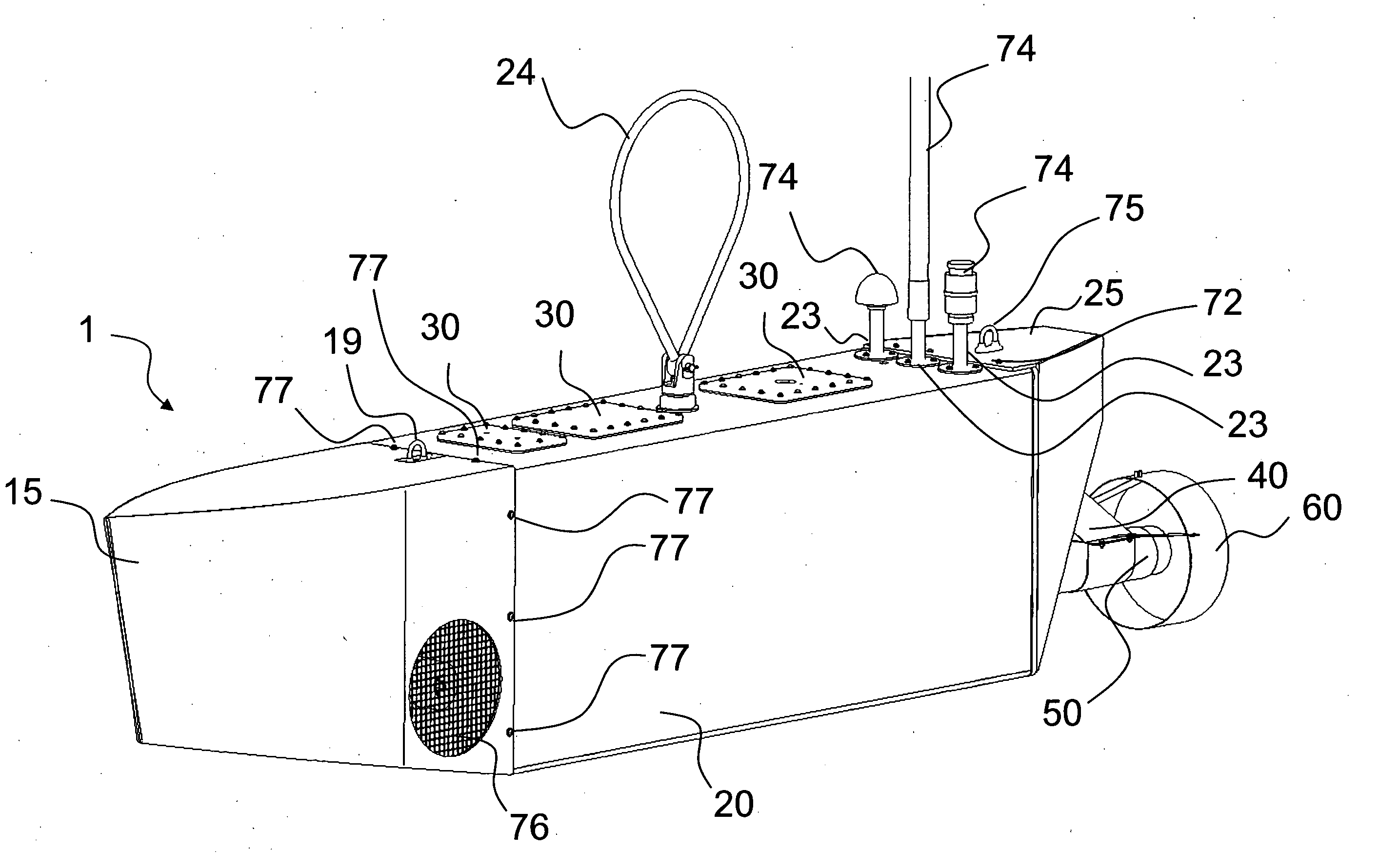
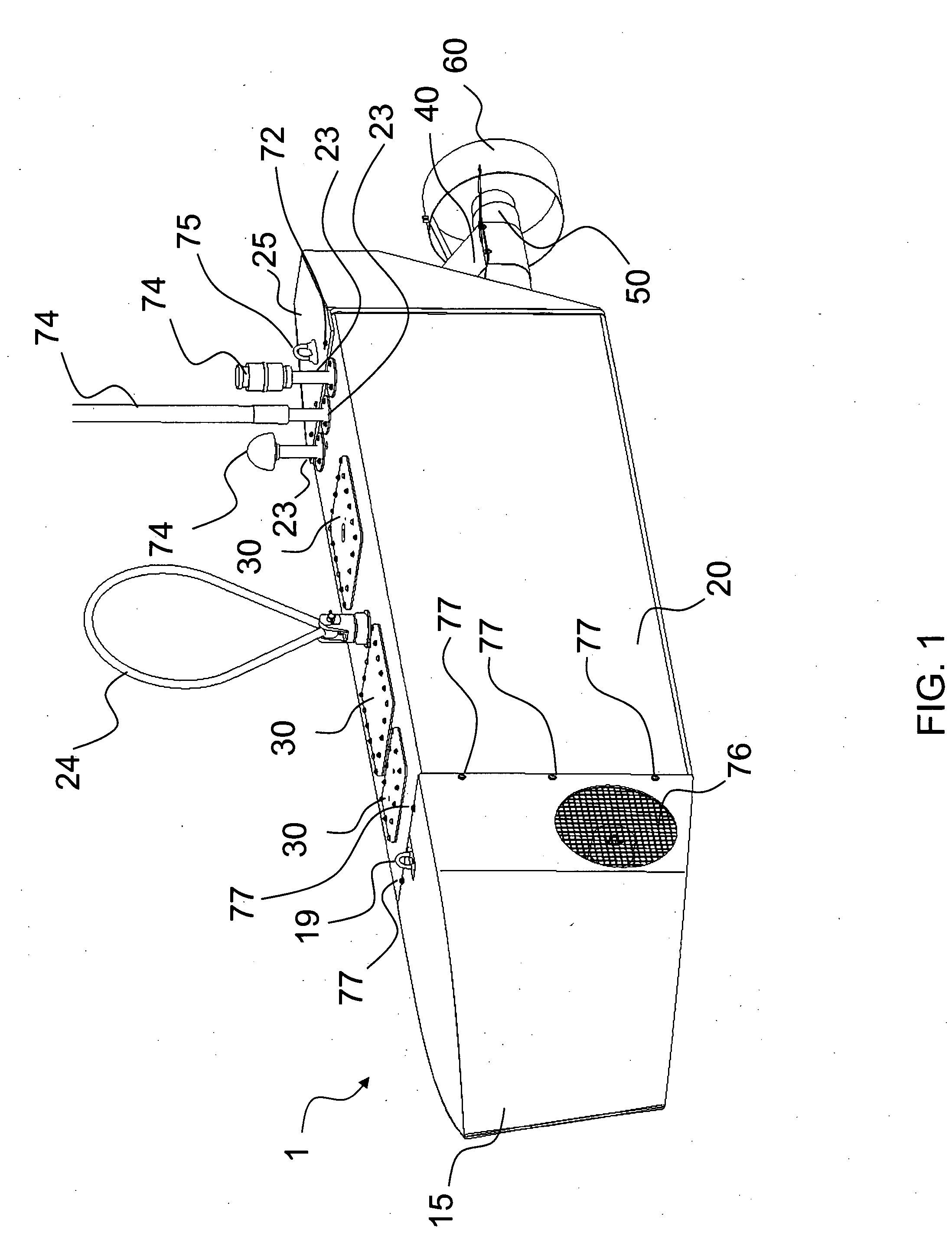
[0073]FIG. 1. is a diagram of a vessel 1 according to an embodiment of the present invention. The vessel is made up of hull segments including a free-flood nose fairing 15, a sealed center section 20 and a free-flood aft fairing 25. An aft thruster 50, mounted on a thruster mounting 40 and using a thruster fairing 60, provides forward thrust. The bow thruster tunnel 76 holds a forward thruster that provides steering. Bolt holes 77 at the forward bulkhead of the sealed center section accept bolts fastening the nose fairing to the center section. Bolt holes 72 at the aft bulkhead of the sealed center section accept bolts fastening the aft fairing to the center section. Removable water tight ports 30 provide access into the sealed center section. A lift ring 24 provides a single point for lifting the entire vessel. A tow point 19 at the forward end provides a single point for towing the vessel. A tie point 75 at the aft end provides a point for guiding the ...


PUM

PropertyMeasurementUnit
Poweraaaaaaaaaa

Abstract

The technical disclosure herein describes an autonomous water-borne vehicle having a segmented non-planing hull with free flood fore and aft sections and a sealed center section. The disclosure also described such a vehicle having a fixed longitudinal thruster and a fixed lateral thruster for changing the heading of the vehicle. The disclosure also described such a vehicle having an autonomous mission system, an autonomous navigation system, and a web-based command and control system. The disclosure also describes such a vehicle having a submersible winch. The disclosure also describes such a vehicle wherein the sealed center section is of substantially rectangular cross section. The disclosure also describes such a vehicle having a wheeled battery tray.

Description

[0001]This application claims the benefit of Provisional Patent Application No. 60 / 778,172, filed Feb. 28, 2006 under 35 U.S.C. 119(e).1. BACKGROUND OF THE INVENTION [0002]1.1. Hull Configuration[0003]A portion of the present invention relates to vessel hulls. More particularly, this portion relates to autonomous water-borne vehicle (AWV) hulls that have modular components and a minimum number of moving parts.[0004]Some AWV designs use existing hull configurations for manned vehicles. This approach reduces the vehicle cost by reducing design costs, but constrains the design to adapt to an existing hull configuration, often yielding undesirable configurations of equipment and sensors. The existing hull configuration may also include a large number of moving parts based on an assumed crew; this may prove unsuitable for unmanned operations without ready local maintenance.[0005]Other AWV hulls rely on custom hull configurations. Though the custom hull yields an optimal design in terms o...

Claims


Application Information

Patent Timeline
IPC IPC(8): G05D1/00
CPCG05D1/0206B63B3/04Y02T70/14B63B2035/007B63H2005/1258B63B5/24Y02T70/10
Inventor SAUNDERS, JIMMY DALERAYMUND, TIMOTHY DANIELSPLAWN, JASON CHRISTOPHERWHITE, SCOTT WILLIAMCAMPBELL, DEBBIE LEEHUYSER, CYNTHIA GAYERUSU, PETREBRUCKS, MARK LEO
Owner J3S
Why Eureka
Try Eureka