Control device for internal combustion engine

Active Publication Date: 2007-09-06
MITSUBISHI ELECTRIC CORP
View PDF7 Cites 4 Cited by
  • Summary
  • Abstract
  • Description
  • Claims
  • Application Information

AI Technical Summary

Benefits of technology

[0035] Therefore, the amount of control of the controlling constants or the combination thereof can be set in accordance with the target average air/fuel ratio, resulting in stable and accurate control of the air/fuel ratio of the exhaust gas on the upstream side of the catalyst.
[0036] By setting the controlling constants with the use of the target average air/fuel ratio as an index, appropriate controlling con

Problems solved by technology

Therefore, the upstream O2 sensor is exposed to the exhaust gas at a high temperature and is poisoned by various toxic substances.
Moreover, since the exhaust gas is not sufficiently mixed at the location close to the combustion chamber, a variation occurs in air/fuel ratio of the exhaust gas.
Therefore, there is a problem in that the output from the upstream O2 sensor greatly fluctuates, making it impossible to accurately control the air/fuel ratio of the exhaust gas.
In addition, toxic substances are absorbed by the catalyst to reduce the effects of the toxic substances.
In the above-described conventional device, however, a common management index is not set.
Therefore, when the air/fuel ratio of the exhaust gas on the upstream side of the catalyst is to be shifted to the lean side

Method used


Image

  • Control device for internal combustion engine
  • Control device for internal combustion engine
  • Control device for internal combustion engine

Examples


Example

First Embodiment

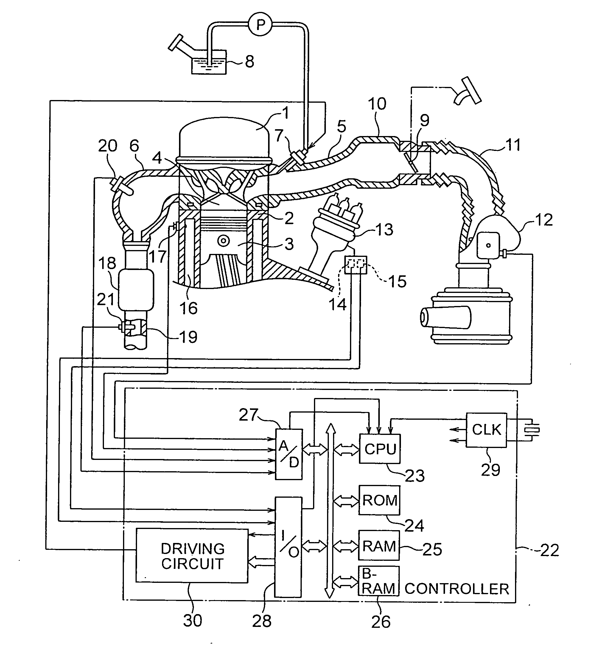
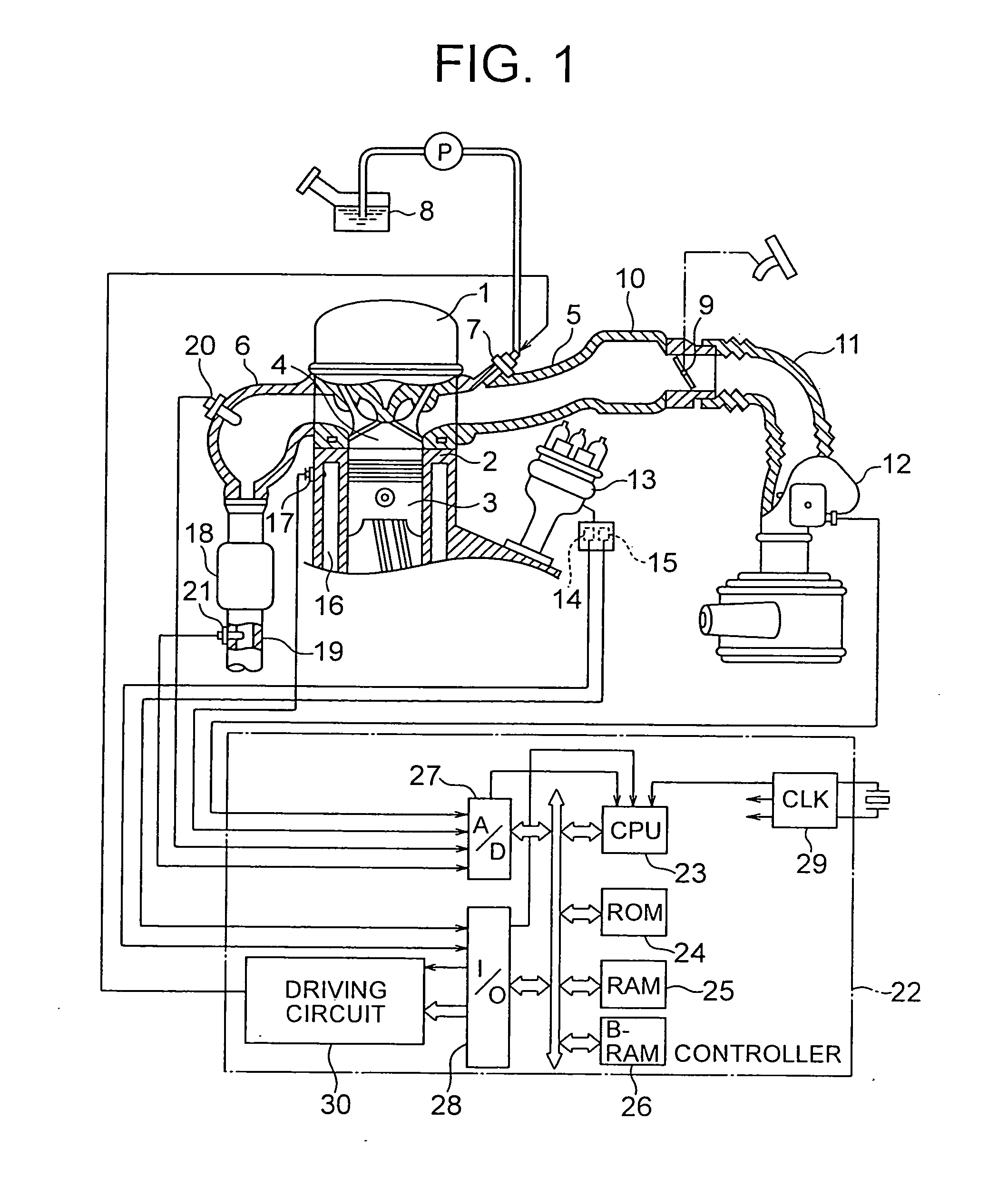
[0079]FIG. 1 is a configuration diagram showing the entire system including a control device for an internal combustion engine according to the first embodiment of the present invention. Although a plurality of cylinders 2 are provided in a general internal combustion engine, only one of the cylinders 2 will be described in the following embodiment.

[0080] In FIG. 1, an engine main body 1 includes a combustion chamber 4 into which an air / fuel mixture is taken for combustion by a cylindrical cylinder 2 and a piston 3 connected to a crank shaft (not shown).

[0081] An intake port 5 for taking air into the cylinder 2 and an exhaust manifold 6 for exhausting an exhaust gas generated by the combustion of the air / fuel mixture in the combustion chamber 4 are connected to the cylinder 2. At the top of the cylinder 2, an ignition plug (not shown) for igniting the air / fuel mixture supplied to the combustion chamber 4 is attached.

[0082] On the downstream side of the intake por...


PUM


Abstract

Provided is a control device for an internal combustion engine, which can enable stable and fine control of an average air/fuel ratio of an exhaust gas on the upstream side of a catalyst. The control device for an internal combustion engine includes: a catalytic converter; an upstream O2 sensor to the upstream of the catalyst; a downstream O2 sensor to the downstream of the catalyst; a first air/fuel ratio feedback control unit for controlling the air/fuel ratio of the exhaust gas based on an output value of the upstream O2 sensor and a controlling constant group; a second air/fuel ratio feedback control unit for calculating a target average air/fuel ratio AFAVEobj based on the output value of the upstream O2 sensor and an output target value VR2; and a conversion unit for calculating at least two controlling constants by using the target average air/fuel ratio AFAVEobj as a common index.

Description

BACKGROUND OF THE INVENTION [0001] 1. Field of the Invention [0002] The present invention relates to a control device for an internal combustion engine, for controlling an air / fuel ratio of an exhaust gas. [0003] 2. Related Background Art [0004] In an exhaust path of a general internal combustion engine, a three-way catalyst for simultaneously cleaning HC, CO, and NOx contained in an exhaust gas is provided. The three-way catalyst exhibits a high cleaning rate for any of HC, CO, and NOx when an air / fuel ratio of the exhaust gas is in the vicinity of a stoichiometric air / fuel ratio. [0005] Therefore, generally, an O2 sensor (hereinafter, referred to as an “upstream O2 sensor”) is provided to an upstream side of the catalyst to perform feedback control based on an output from the upstream O2 sensor so that the air / fuel ratio of the exhaust gas becomes closer to the stoichiometric air / fuel ratio. [0006] However, the upstream O2 sensor is provided in the exhaust path as close to a combu...

Claims


Application Information

Patent Timeline
IPC IPC(8): F01N3/00F02D41/14
CPCF02D41/0235F02D41/1401F02D2041/1422F02D41/1488F02D2041/1418F02D41/1441
Inventor TAKUBO, HIDEKI
Owner MITSUBISHI ELECTRIC CORP
Why Eureka
Try Eureka