
Split-cycle engine with disc valve

a technology of disc valve and split-cycle engine, which is applied in the direction of valve arrangement, combustion engine, machine/engine, etc., can solve the problems of increasing friction of the split-cycle engine and reducing volumetric efficiency, so as to reduce the volume of air left, increase the compression ratio and volumetric efficiency, and reduce the displacement of the cylinder

Inactive Publication Date: 2007-09-06
SKADERI GRUP LLC
View PDF1 Cites 7 Cited by
  • Summary
  • Abstract
  • Description
  • Claims
  • Application Information

AI Technical Summary

Benefits of technology

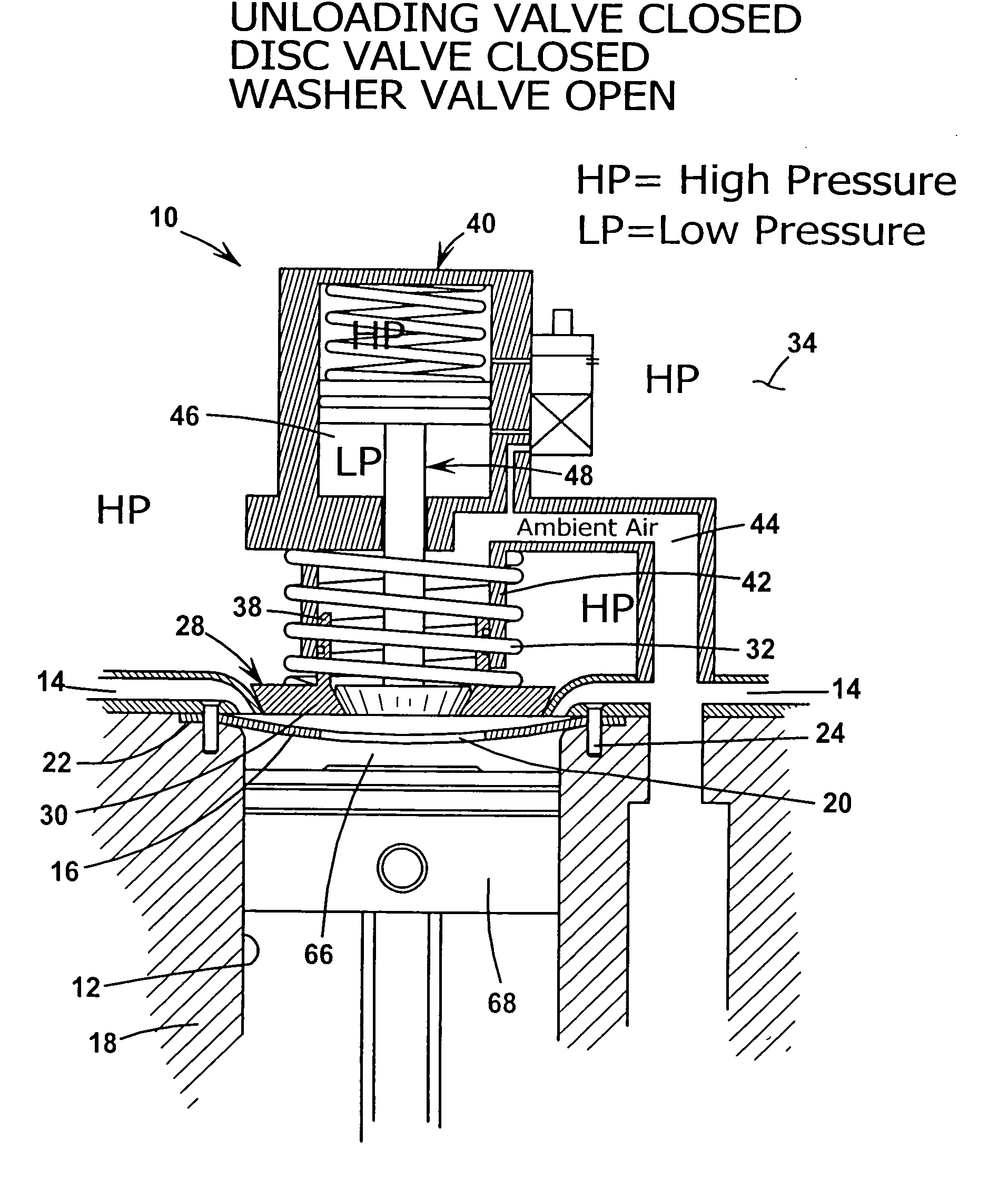
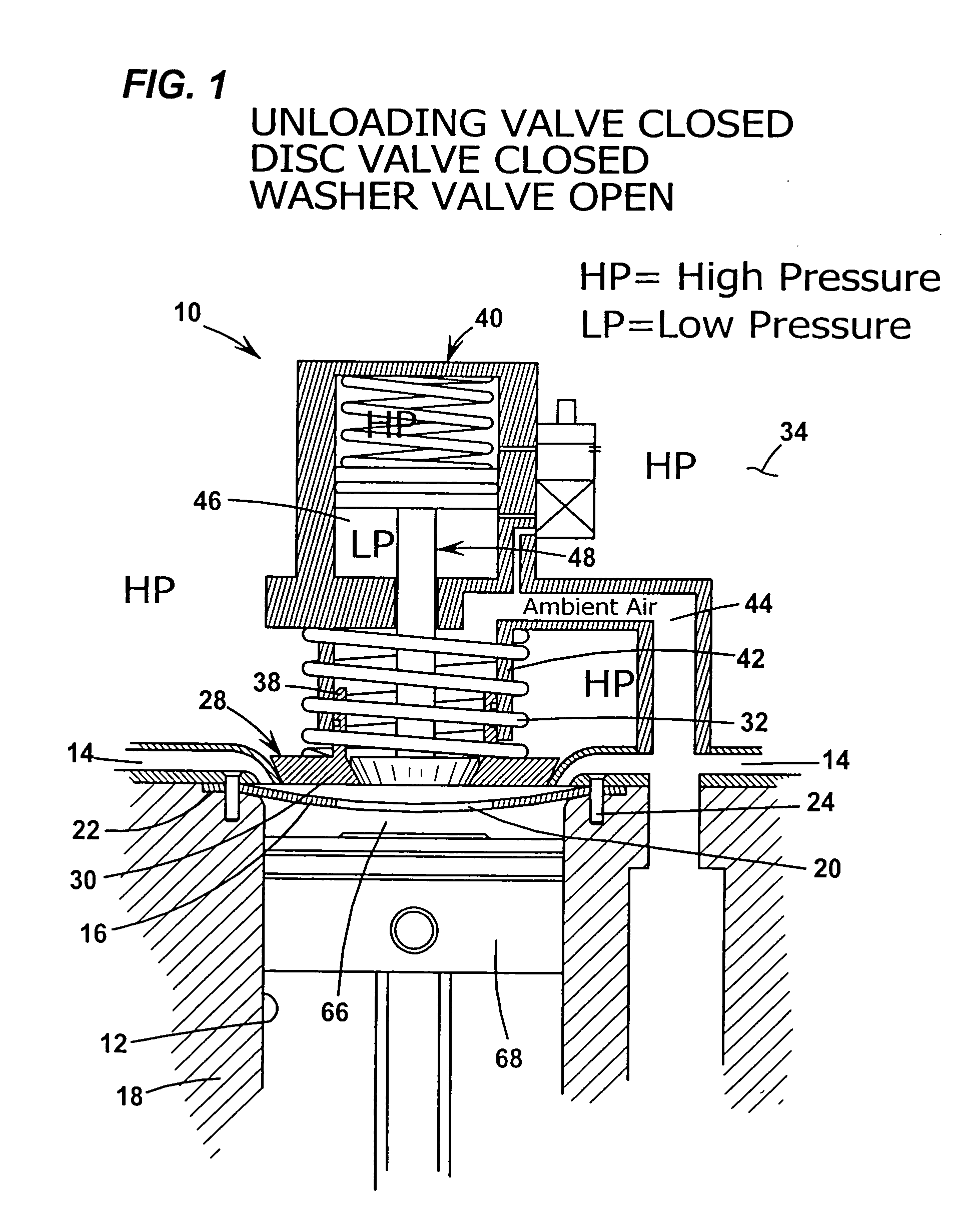
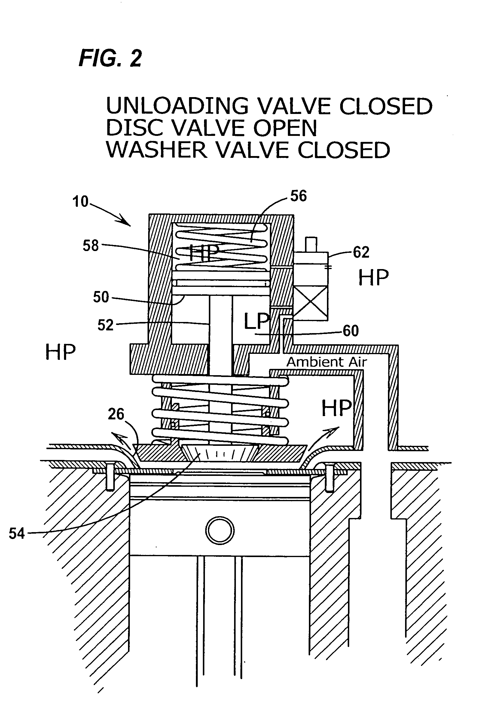
[0019]The present invention provides a disc valve assembly (disc valve) that is both a check valve for the gas passage inlet and a flow control valve for the compression cylinder ambient air inlet. The disc valve assembly generally includes a disc valve outlet that is a check valve for the gas passage inlet and a disc valve inlet that is a washer valve (also referred to as a reed type or ring type suction valve) for the compression cylinder air inlet. The washer valve is also a check-type valve that only allows one-way flow of gases. The disc valve assembly may also include an unloading valve. The disc valve assembly reduces the TDC piston-to-cylinder head (p-h) clearance, thereby reducing the volume of air left in the p-h clearance, i.e. dead space, and increasing the compression ratio and volumetric efficiency. The reduction of p-h clearance also can reduce the cylinder displacement required to achieve a given power and torque level.
[0020]A Disc Valve Study is incorporated herein, which shows significant potential improvement of the performance of a split-cycle engine utilizing a disc valve in its compression cylinder. More specifically, the Disc Valve Study illustrates that a disc valve used to replace the intake valves and check valves on the compression cylinder may allow for significant reduction of the piston to head clearance. Additionally, a disc valve with a low disc valve inlet delta pressure (e.g., approximately 0.2 bar or less) and a low piston to head clearance (e.g., approximately 0.25 mm or less) has the potential to significantly increase Indicated Thermal Efficiency (ITE) and Indicated Mean Effective Pressure (IMEP) of the engine.

Problems solved by technology

This added volume decreases volumetric efficiency and increases friction of the split-cycle engine.

Method used


Image

  • Split-cycle engine with disc valve
  • Split-cycle engine with disc valve
  • Split-cycle engine with disc valve

Examples


Embodiment Construction

[0033]Referring now to the drawings in detail, numeral 10 generally indicates an exemplary embodiment of a split-cycle engine having a disc valve in accordance with the invention. Engine 10, shown schematically, is generally of the split-cycle type such as that disclosed in U.S. Pat. Nos. 6,543,225, 6,609,371, and 6,952,923 (Scuderi patents), herein incorporated by reference in their entirety.

[0034]Referring to FIGS. 1-3, an exemplary embodiment of a disc valve for a split-cycle engine is shown generally at 10. The engine cylinder head (not shown) includes a generally circular opening circumscribing a periphery of the compression cylinder 12 and defining the compression cylinder air inlet passage 14. The disc valve assembly 10 includes a disc valve inlet that is an annular ring 16 disposed between the engine block 18 and the cylinder head about the compression cylinder air inlet passage 14 for opening and closing the compression cylinder air inlet passage 14. The annular ring 16 con...


PUM


Abstract

A split-cycle engine with disc valve includes a crankshaft, a power cylinder and a compression cylinder. A gas crossover passage interconnects the compression cylinder and the power cylinder. An air intake port circumscribes a periphery of the compression cylinder and defines an outer valve seat. An annular ring having a generally central opening is disposed between the compression cylinder and the air intake port and forms a washer valve for opening and closing the air intake port. A disc valve member is concentrically mounted over the central opening of the annular ring. The disc valve member includes a piston portion having a sidewall biased into engagement with the outer valve seat for controlling flow between the compression cylinder and the gas crossover passage.

Description

CROSS REFERENCE TO RELATED APPLICATION[0001]This application claims the benefit of U.S. Provisional Application No. 60 / 778,049, filed Mar. 1, 2006.TECHNICAL FIELD[0002]This invention relates to split-cycle engines and, more particularly, to such an engine incorporating a disc valve.BACKGROUND OF THE INVENTION[0003]The term split-cycle engine as used in the present application may not have yet received a fixed meaning commonly known to those skilled in the engine art. Accordingly, for purposes of clarity, the following definition is offered for the term split-cycle engine as may be applied to engines disclosed in the prior art and as referred to in the present application.[0004]A split-cycle engine as referred to herein comprises:[0005]a crankshaft rotatable about a crankshaft axis;[0006]a power piston slidably received within a power cylinder and operatively connected to the crankshaft such that the power piston reciprocates through a power (or expansion) stroke and an exhaust strok...

Claims


Application Information

Patent Timeline
Patent Type & Authority Applications(United States)
IPC IPC(8): F02B33/00
CPCF01L1/36F01L1/46F01L3/205F02B33/06F01L2800/10F01L2820/01F01L7/06F01L2003/258
Inventor SCUDERI, SALVATORE C.
Owner SKADERI GRUP LLC
Learn More