Heat sink with a centrifugal fan

a centrifugal fan and heat sink technology, which is applied in the field of heat sinks, can solve the problems of heat sinks, difficult to produce fins with fine pitch, and restricted pitch between fins, and achieve the effect of effectively lowering the temperature within the box, excellent heat dissipation, and low sound nois

Active Publication Date: 2007-09-06
FURUKAWA ELECTRIC CO LTD
View PDF16 Cites 8 Cited by
  • Summary
  • Abstract
  • Description
  • Claims
  • Application Information

AI Technical Summary

Benefits of technology

[0010]One of the objects of the invention is to provide a compact heat sink with a centrifugal fan having a low sound noise and excellent in heat dissipation, which can more effectively lower the temperature within a box as a whole, even when it is used in an electronics device, the height of which is limited such as a personal computer, a game equipment or the like.

Problems solved by technology

However, the heat sink made of aluminum extruded material has a technical problem in which the pitch between the fins is restricted to a certain degree due to the manufacturing technology, thus fins with fine pitch are difficult to be produced.
It is difficult to satisfy the increase of the amount of the generated heat by the combination of the heat receiving block and the heat dissipating fins, resulting in the heat sink with the use of the heat pipe.
In order to cool the heat sink with the thin fins of the size horizontally wide, many fans with small diameter has to be installed, thus the number of the fans becomes large to result in the large noise.
Furthermore, the size of the air discharge port becomes large, leading to the large size of the box with various terminals appropriately arranged.

Method used


Image

  • Heat sink with a centrifugal fan
  • Heat sink with a centrifugal fan
  • Heat sink with a centrifugal fan

Examples


Embodiment Construction

[0036]The heat sink with a centrifugal fan of the invention is described in detail with reference to the drawings.

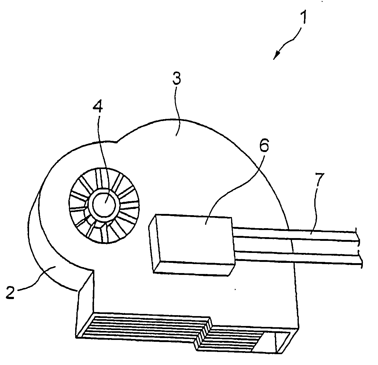
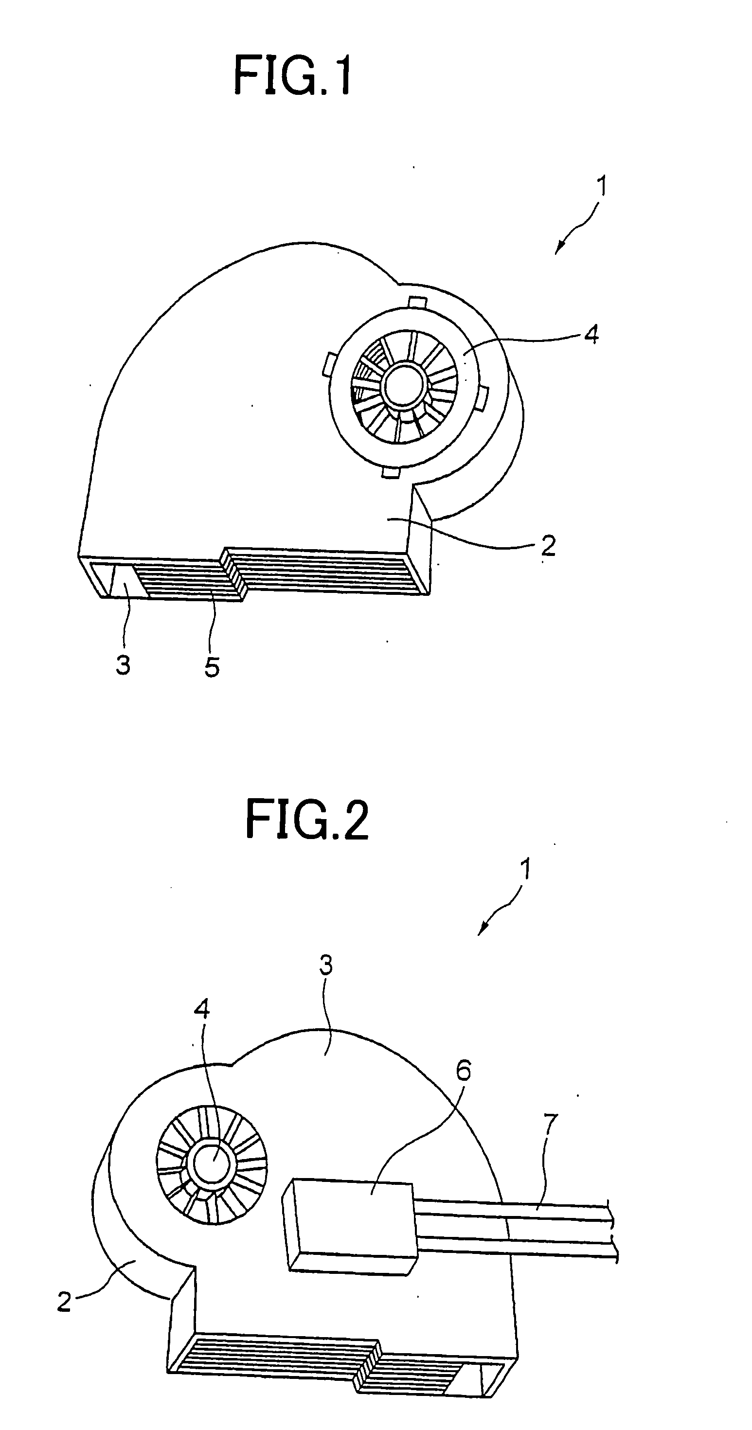
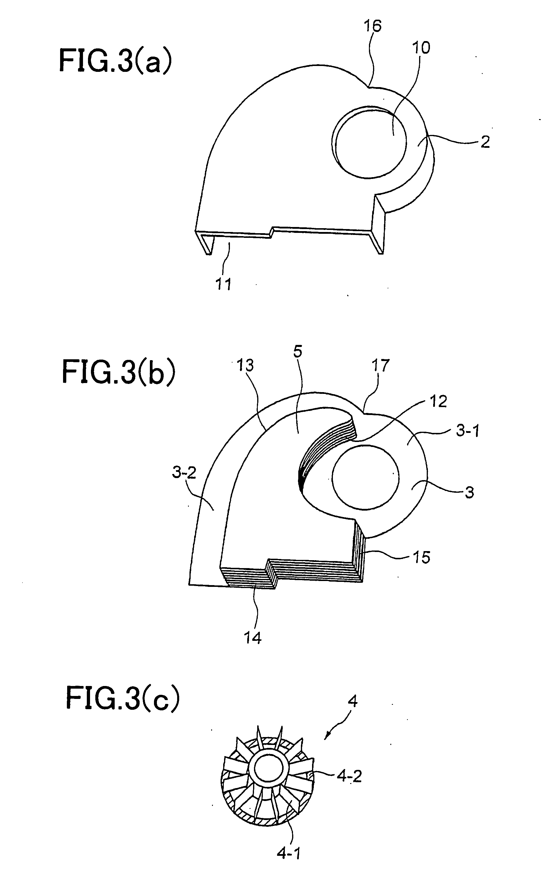
[0037]One embodiment of the heat sink with a centrifugal fan comprises: a cover of a prescribed shape including an air intake port and an air discharge port; a heat receiving block thermally connected to a heat generating part to be cooled; a bottom portion which is excellent in heat transferability, thermally connected to one face of said heat receiving block, and engaged to said cover to form a space portion; a heat dissipating fin portion comprising a plurality of fins, received within the space portion, thermally connected to said bottom portion, and having a prescribed shape including at least an air inflow portion; and a centrifugal fan, a rotating shaft of which is arranged in a vicinity of the air inflow portion of said heat dissipating fin portion, which intakes air from the air intake port, generates an air flow through spaces formed between adjacent fins of sa...


PUM


Abstract

A heat sink with a centrifugal fan comprising: a cover of a prescribed shape including an air intake port and an air discharge port; a heat receiving block thermally connected to a heat generating part to be cooled; a bottom portion which is excellent in heat transferability, thermally connected to one face of said heat receiving block, and engaged to said cover to form a space portion; a heat dissipating fin portion comprising a plurality of fins, received within the space portion, thermally connected to said bottom portion, and having a prescribed shape including at least an air inflow portion; and a centrifugal fan, a rotating shaft of which is arranged in a vicinity of the air inflow portion of said heat dissipating fin portion, which intakes air from the air intake port, generates an air flow through spaces formed between adjacent fins of said heat dissipating fin portion, and generates another air flow along an inner wall of said cover toward said air discharge port.

Description

BACKGROUND OF THE INVENTION[0001]1. Field of the Invention[0002]The present invention relates to a heat sink with a plurality of heat dissipating fins and centrifugal fan, and in particular to a compact heat sink with centrifugal fan excellent in heat transfer efficiency which has a large amount of ventilation.[0003]2. Description of the Related Art[0004]Since the heat density of the devices and the heat generated by the CPU, devices or the like increases, it is desired that a heat sink excellent in heat dissipating efficiency with high performance is developed. Furthermore, since the height of the electronics devices such as a personal computer, game device or the like is limited, it is desired that a compact heat sink excellent in heat dissipating efficiency with low noise is developed. A heat sink made of aluminum extruded material with low manufacturing cost has been widely used. Since the heat sink made of aluminum extruded material is manufactured as one unit in which the heat...

Claims


Application Information

Patent Timeline
Patent Type & Authority Applications(United States)
IPC IPC(8): H05K7/20
CPCH01L23/467H01L2924/0002H01L2924/00
Inventor UCHIMURA, YASUHIROSASAKI, CHIYOSHIHASHIMOTO, NOBUYUKI
Owner FURUKAWA ELECTRIC CO LTD
Why Eureka
Try Eureka