Electrophoresis member, production thereof and capillary electrophoresis apparatus

a technology of electrophoresis and electrophoresis chamber, which is applied in the direction of fluorescence/phosphorescence, liquid/fluent solid measurement, peptides, etc., can solve the problems of low irradiation efficiency, low analyzing sensitivity, and limited heat generation voltage, etc., to achieve compact capillary array, high heat releasability, and accurate

a technology of electrophoresis and electrophoresis chamber, which is applied in the direction of fluorescence/phosphorescence, liquid/fluent solid measurement, peptides, etc., can solve the problems of low irradiation efficiency, low analyzing sensitivity, and limited heat generation voltage, etc., to achieve compact capillary array, high heat releasability, and accurate

US20070205105A1Inactive Publication Date: 2007-09-06HITACHI LTD +1

Image

  • Electrophoresis member, production thereof and capillary electrophoresis apparatus
  • Electrophoresis member, production thereof and capillary electrophoresis apparatus
  • Electrophoresis member, production thereof and capillary electrophoresis apparatus

Examples


examples 1 and 2

Example 1

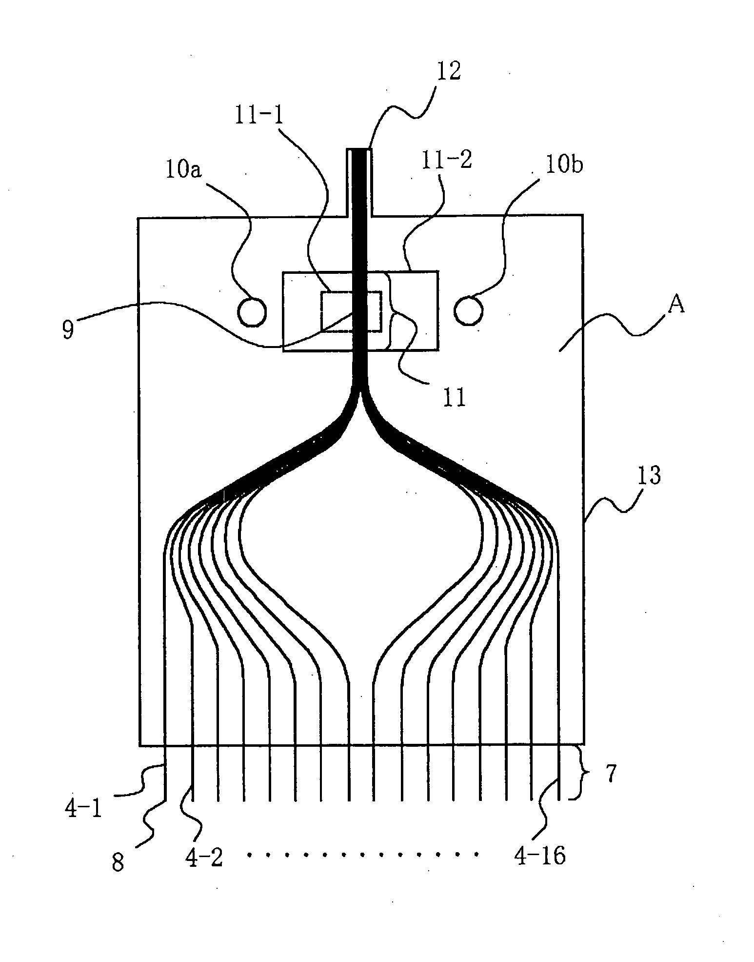
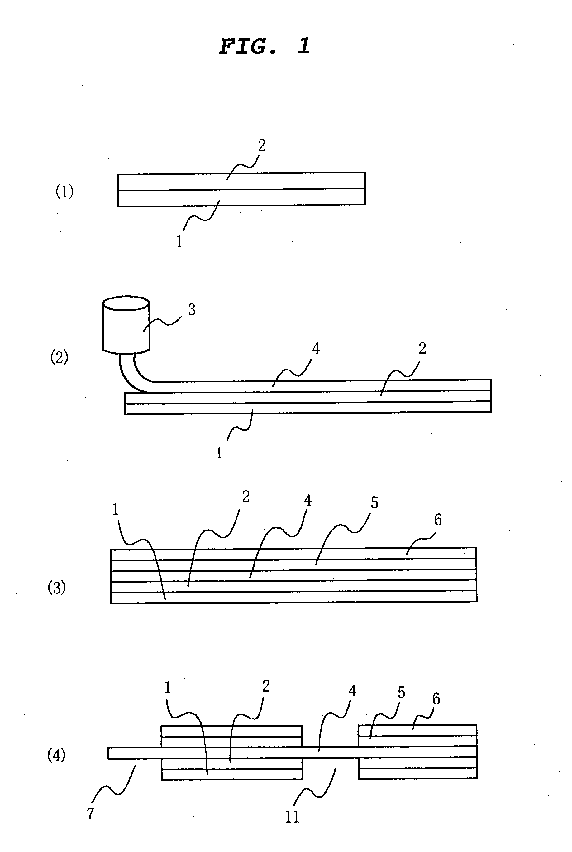
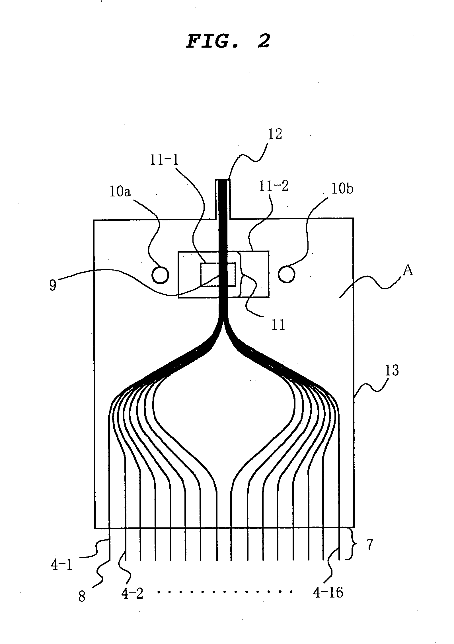
[0061]FIG. 1 shows the production process employed in this example. CAPTON 300H (75 μm thick, trade name, produced by E. I. Du Pont de Nemours and Company) was used as the first support layer 1, and a silicone adhesive sheet S9009 (100 μm thick, trade name, produced by Dow Corning Asia Co., Ltd.) was used as the first adhesive layer 2 on one surface of the first support layer 1. A laying apparatus 3 (produced by Hitachi Chemical Co., Ltd.) that numerically controls applied load and the movement of an X-Y table was used to lay sixteen glass capillaries 4 (4-1-4-16) coated with polyimide resin (Trade name: TSP050150, produced by Polymicro Technologies Co., Ltd., outside diameter: 150 μm, inside diameter: 50 cm) on the first adhesive layer 2 so that the detection parts 9 were 20 cm distant from the terminating ends 8 of the sample injection portion 7. Load of 100 g was applied on the capillaries being laid. CAPTON 300H (75 μm thick, trade name, produced by E. I. Du Pont de Ne...

example 2

[0074]FIG. 7 shows an electrophoresis member of a second example according to the invention. In this example, the glass capillaries are supported before and behind the detection part 9 by a second supporter 40 (made of a plastic) having finely V-grooves for keeping the parallel capillary alignment. This made the intensity of the light irradiated to the capillaries more uniform to decrease its dispersion within ±10%. Further, the structure of the measuring system was simplified by removing the first support layer 1, the first adhesive layer 2, the second adhesive layer 5 and the second support layer 6 at all of the part opposing to the sample injection portion 7 of the capillaries 4 and including the detection parts 9. 41 is a cylindrical ferrule having a penetrating hole. The capillaries are bundled and inserted into the hole, and gaps are filled with an adhesive. The cylindrically bundled ends of the capillary array allow easy sealing, enabling filling the electrophoresis medium in...


PUM

PropertyMeasurementUnit
diameteraaaaaaaaaa
thicknessaaaaaaaaaa
thickaaaaaaaaaa

Abstract

An electrophoresis member is produced by laying a plurality of capillaries on an adhesive layer born on a support layer to form a capillary layer, laminating thereon a second support layer, and partially removing the first support layer, the first adhesive layer and the second support layer to partially expose the capillaries to form a window portion for irradiation and detection and a sample injection portion for injecting a sample.

Description

BACKGROUND OF THE INVENTION [0001] (a) Field of the Invention [0002] The present invention relates to an electrophoresis apparatus used for analyzing polymers, such as DNA, RNA and proteins, particularly, an electrophoresis member used in DNA sequencers, and to its production. [0003] (b) Description of the Related Art [0004] According to one technique of DNA sequencing, a liquid containing DNA fragments is separated by electrophoresis to detect the fluorescence of each DNA fragment. A conventional method is a slab gel electrophoresis method wherein electrophoresis is conducted in a gel filled between glass plates. Decreased gel thickness and higher voltage are necessary to speed up the electrophoresis separation, but generation of heat has limited the applicable voltage. [0005] A new technique is a capillary electrophoresis method using quartz capillaries of about 10 to 100 μm in inside diameter. Because capillaries decrease the generation of heat, higher voltage can be applied as c...

Claims


Application Information

Patent Timeline
06 Sep 2007
Publication
US20070205105A1
IPC
B01D57/02; G01N27/447; G01N21/64
CPC
G01N27/44782
Inventors
KAWAZOE, HIROSHI; KAMATA, TOMOYUKI