Folding frame for mounting an antenna

a technology for mounting frames and antennas, which is applied in the direction of collapsible/retractable loop antennas, resonant antennas, and collapsible antennas, etc., can solve the problems of time-consuming assembly of components on the job site, large assembly size of components, and difficulty in assembly, so as to achieve convenient movement, improve the effect of appearance and durability

Active Publication Date: 2007-09-06
VALMONT INDUSTIES INC
View PDF12 Cites 20 Cited by
  • Summary
  • Abstract
  • Description
  • Claims
  • Application Information

AI Technical Summary

Benefits of technology

[0011] A further object of the invention is to provide a folding frame which may be easily moved from its folded position to its unfolded or extended position so that the folding frame may be secured to an upstanding support structure such as a tower, pole, etc.
[0012] Still another object of the invention is to provide a folding frame for mounting an antenna on an upstanding support structure which, in its installed position, is extremely durable in use and refined in appearance.

Problems solved by technology

If the mounting assembly is partially or completely assembled at the factory, the assembled size thereof creates shipping problems.
If the mounting assemblies are shipped to the job site in an unassembled condition, the components thereof must be assembled at the job site which is time-consuming.
Although the Andrew Corporation Quik-Tee Sector Frame, after being assembled, may be folded to reduce its shipping size, applicant believes that the Andrew Corporation structure, in its folded position, is still too large for convenient shipping and that the Andrew Corporation structure, in its non-folded position, may not be as structurally sound as is desirable.
The commonly used single support arm design is prone to twist causing permanent deformation and possible failure when a man load is applied at the ends of each face.

Method used


Image

  • Folding frame for mounting an antenna
  • Folding frame for mounting an antenna
  • Folding frame for mounting an antenna

Examples


Embodiment Construction

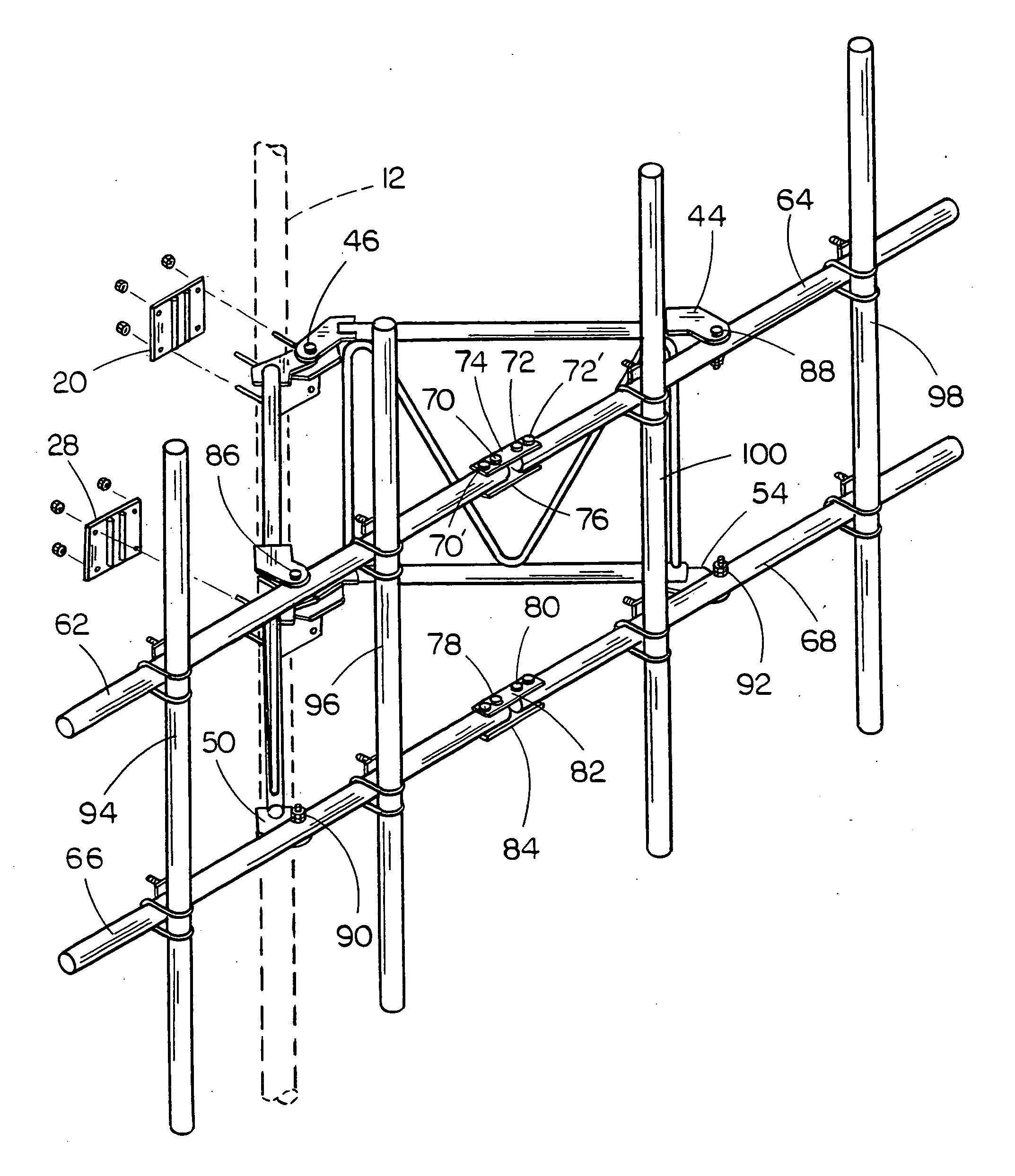
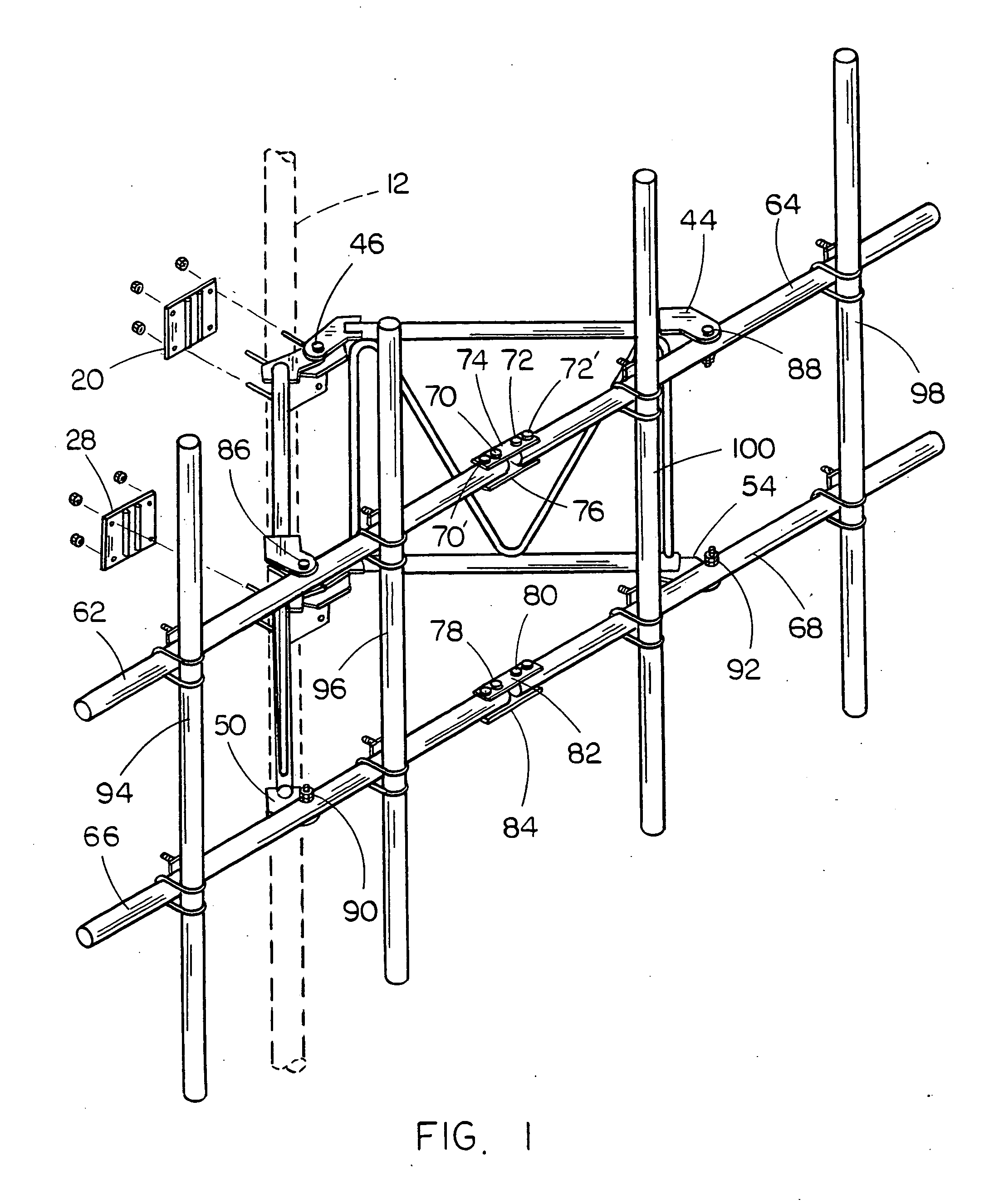
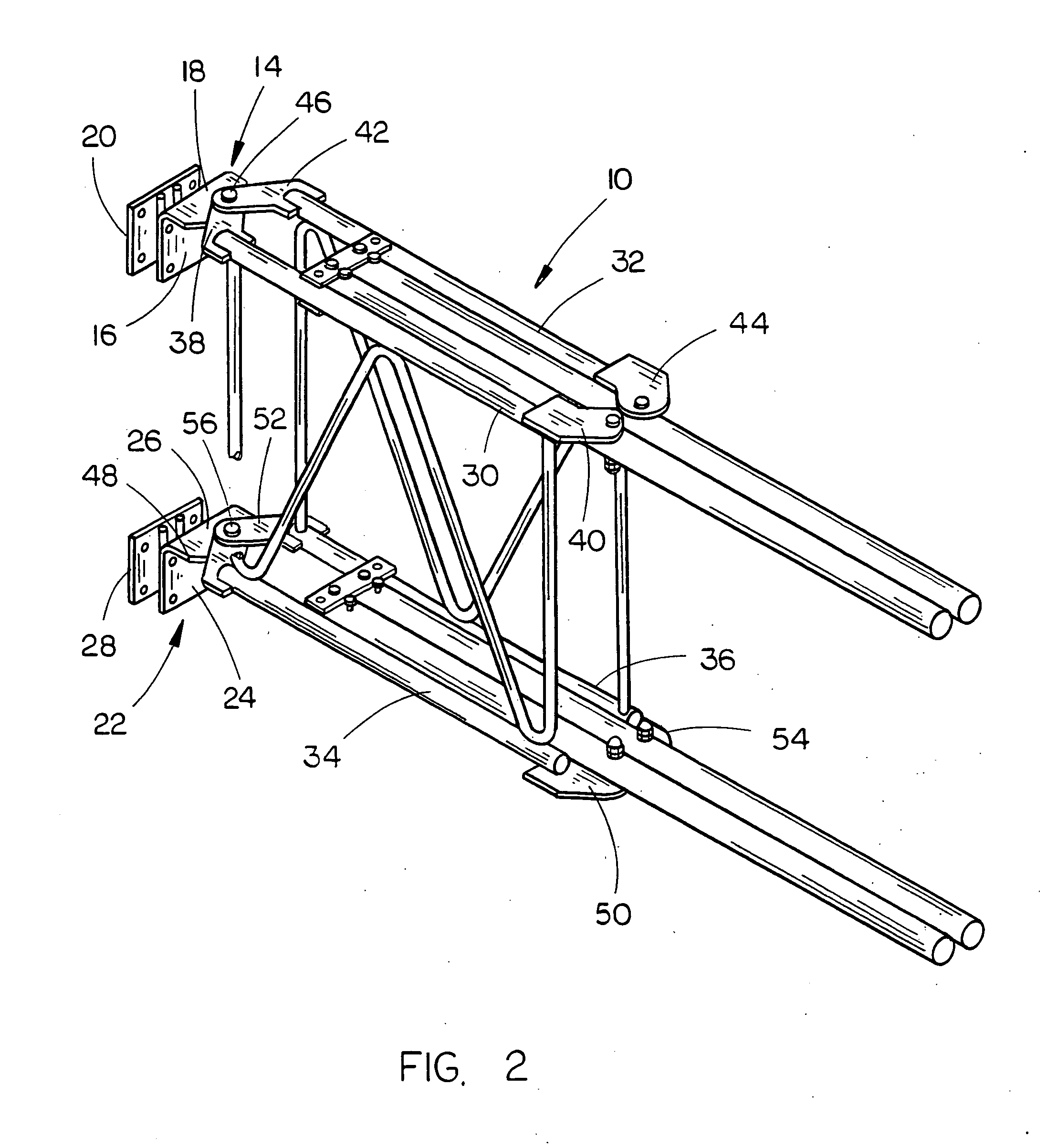
[0019] The folding frame of this invention which is used for mounting an antenna on an upstanding support structure is referred generally by the reference numeral 10. The frame 10 is adapted to be mounted on a vertically disposed support member, structural member or leg such as found in a tower, pole, structural member, etc., as identified by the reference numeral 12. Normally, the support structure 12 will be substantially vertically disposed but may be inclined with respect to vertical or may be tapered.

[0020] The numeral 14 refers to an upper mounting bracket which is adapted to be secured to the support structure 12. Bracket 14 includes a base portion 16 having a top portion 18 extending outwardly therefrom. Base portion 16 is positioned at the outer side of the support structure and a clamp plate 20 is positioned at the inner side of the support structure so that bolts may be extended through the base portion 16 and the clamp plate 20 to secure the upper bracket 14 to the supp...


PUM


Abstract

A folding frame for mounting an antenna on an upstanding support structure including first and second support arms pivotally secured to an upper mounting bracket and third and fourth support arms which are pivotally secured to a lower mounting bracket with the upper and lower mounting brackets being secured to the support structure. Support members are pivotally secured to the outer ends of the support arms and are pivotally connected together so that the frame may be pivotally moved from a folded position to a non-folding position. When the frame is in its folded position, it is easily shipped on a pallet.

Description

BACKGROUND OF THE INVENTION [0001] 1. Field of the Invention [0002] This invention relates to a folding frame for mounting an antenna and more particularly to a folding frame for mounting an antenna on an upstanding support structure such as a tower, pole or the like. [0003] 2. Description of the Related Art [0004] Wireless communication antennas are commonly mounted on upstanding support structures such as towers, poles, etc., to optimize signal reception and transmission. The antennas may be secured to the support structures by a variety of different mounting assemblies or mounts. Some of the mounts are commonly referred to as a T-frame mount, a V-frame mount, standoff sector mount, etc. The prior art mounting assemblies or mounts may be partially assembled at the factory and shipped to the job site on a pallet or the like or may be shipped to the job site in an unassembled manner. If the mounting assembly is partially or completely assembled at the factory, the assembled size the...

Claims


Application Information

Patent Timeline
Patent Type & Authority Applications(United States)
IPC IPC(8): H01Q7/02
CPCH01Q1/1235H01Q1/1228
Inventor CHAPMAN, BRANDON M.
Owner VALMONT INDUSTIES INC
Why Eureka
Try Eureka