Image monitoring system and image monitoring program

a monitoring system and image technology, applied in the field of image monitoring systems and image monitoring programs, can solve the problems of excessive load applied to the system, heavy system load, etc., and achieve the effects of reducing the consumption of system resources for detecting moving objects, reducing the load of the process of detecting moving objects, and improving overall performan

Active Publication Date: 2007-09-06
SONY CORP
View PDF4 Cites 14 Cited by
  • Summary
  • Abstract
  • Description
  • Claims
  • Application Information

AI Technical Summary

Benefits of technology

[0011] According to an embodiment of the invention, in the process of detecting a moving object from an image by moving-object detecting means, an image with a resolution lower than that of the image captured by the camera, and moving-object detection is performed using the low-resolution image. Thus the load of the process of detecting a moving object can be reduced.
[0012] Accordingly, in the image monitoring system with a moving-object detecting function according to the embodiments of the invention, consumption of system resources for detecting a moving object can be reduced and the overall performance can be improved.

Problems solved by technology

However, such moving-object detecting function uses many CPUs and memory resources because all the images sent from cameras one by one are subjected to operations, resulting in application of a heavy load on the system.
Particularly, with network-ready image monitoring systems to which a plurality of cameras can be connected, when moving-object detection is carried out for all the images sent from the cameras via a network, an excessive load will be applied to the systems.

Method used


Image

  • Image monitoring system and image monitoring program
  • Image monitoring system and image monitoring program
  • Image monitoring system and image monitoring program

Examples


Embodiment Construction

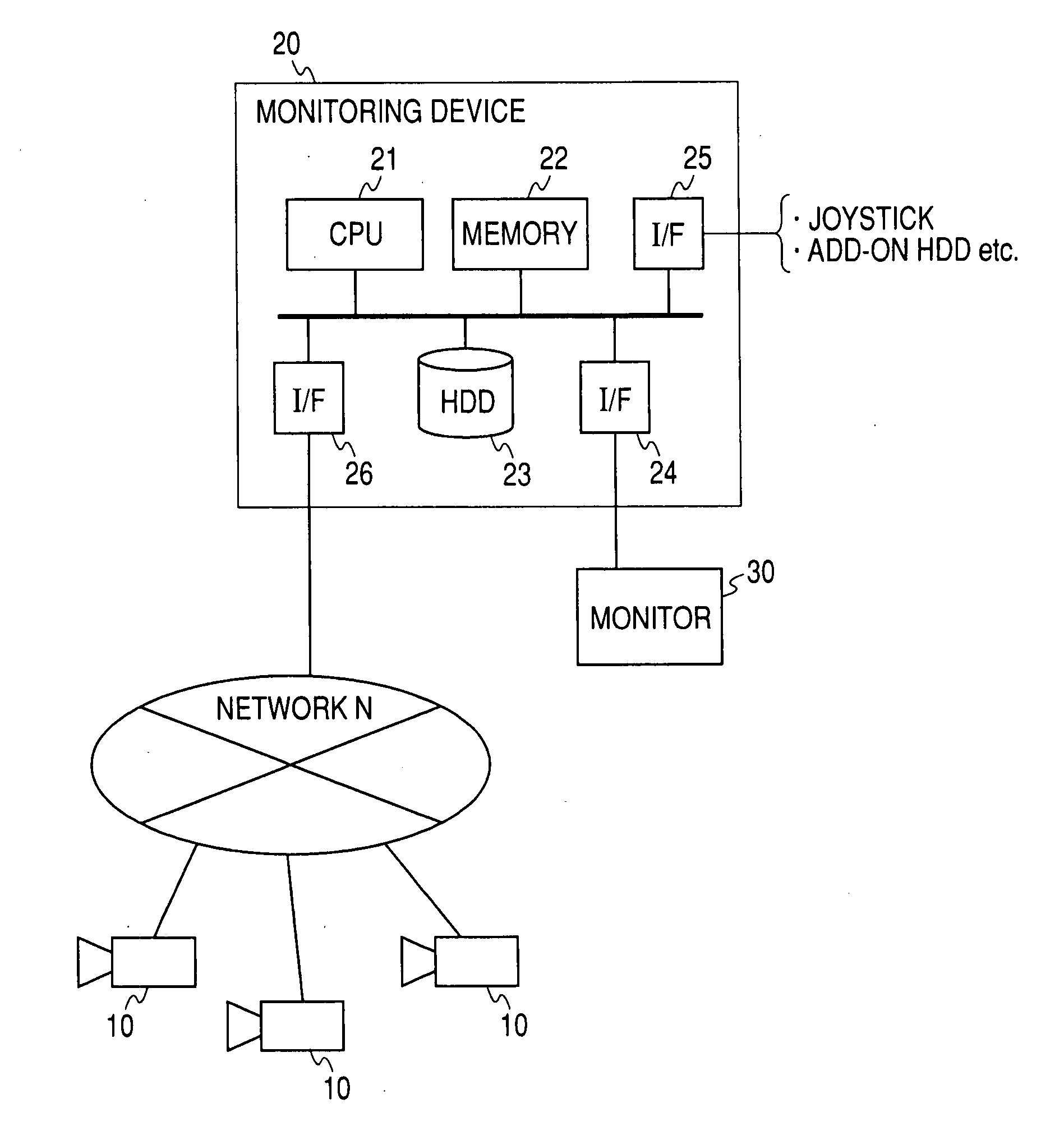
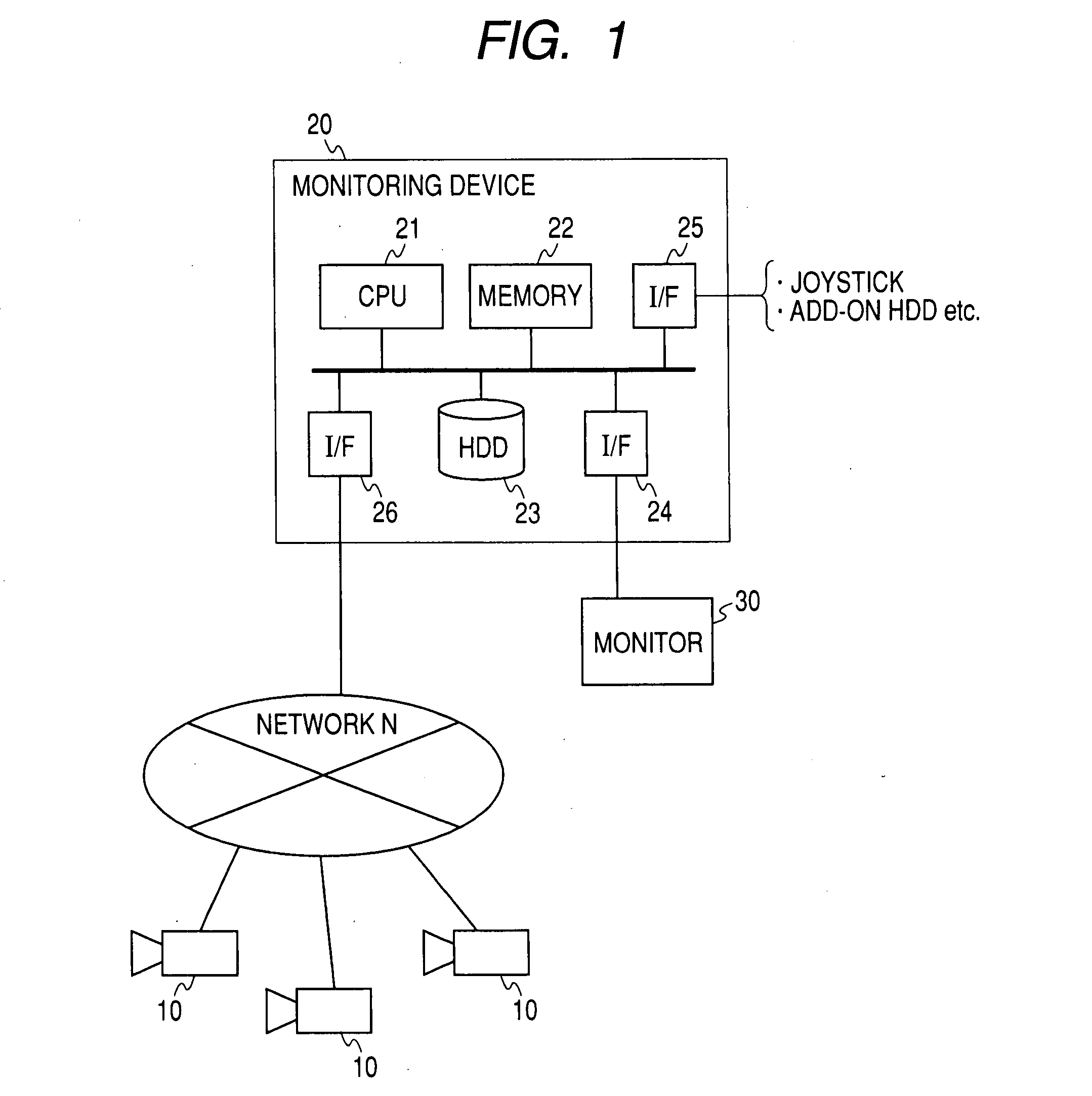
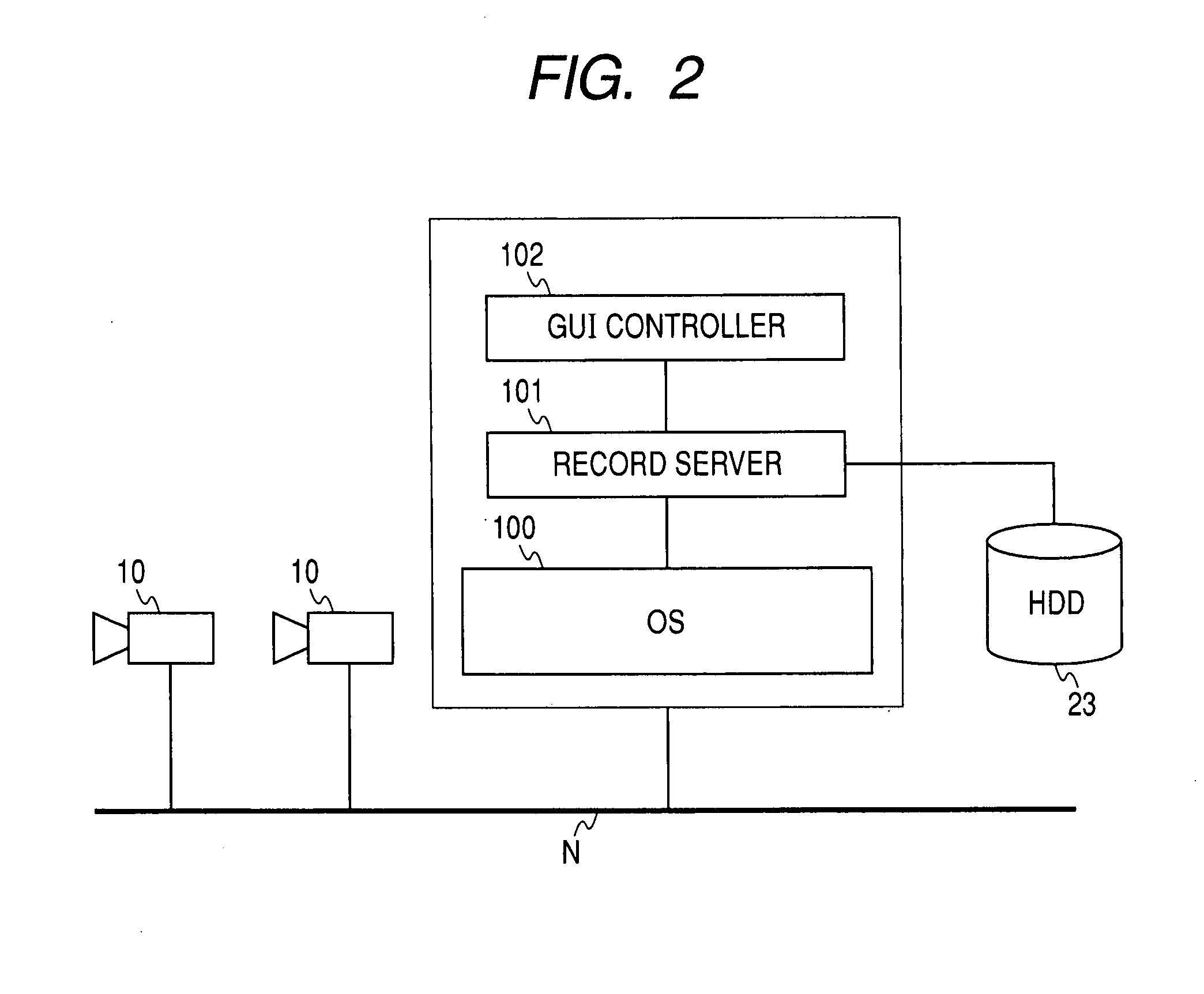
[0018] An embodiment of the invention will be described hereinbelow with reference to the drawings. FIG. 1 is a schematic diagram of the structure of an image monitoring system according to the embodiment; and FIG. 2 is a schematic diagram of the structure of an image monitoring program according to the embodiment.

[0019] As shown in FIG. 1, the image monitoring system according to the embodiment includes a camera 10 (or more) connected to a network N, a monitoring device 20 connected to the network N, and a monitor (display means) 30 connected to the monitoring device 20. The image monitoring system sends an image captured by the camera 10 to the monitoring device 20 in a specified data format (for example, Joint Photographic Experts Group (JPEG) or Moving Picture Experts Group phase 4 (MPEG-4) via the network N to allow the present image to be displayed on the monitor 30 connected to the monitoring device 20, and the sent image to be recorded on a hard disk drive (HDD) 23 which is...


PUM


Abstract

An image monitoring system includes: recording means for recording an image captured by a camera via a network; control means for controlling the system so as to display the present image captured by the camera or a past image recorded on the recording means on display means; and moving-object detecting means for detecting a moving object from the image captured by the camera; wherein the moving-object detecting means includes resolution conversion means for generating an image with a resolution lower than the resolution of the image captured by the camera, positional-information output means for detecting a moving object from the image generated by the resolution conversion means and outputting positional information on the detected moving object, and information merging means for merging the positional information of the moving object with the image captured by the camera on the basis of the positional information of the moving object output by the positional-information output means.

Description

CROSS REFERENCES TO RELATED APPLICATIONS [0001] The present invention contains subject matter related to Japanese Patent Application JP 2006-059261 filed in the Japanese Patent Office on Mar. 6, 2006, the entire contents of which being incorporated herein by reference. BACKGROUND OF THE INVENTION [0002] 1. Field of the Invention [0003] The present invention relates to an image monitoring system and an image monitoring program that can display an image in a camera connected to a network and that can record and reproduce the captured image, and in particular, it relates to an image monitoring system and an image monitoring program equipped with the function of detecting a moving object in the captured image. [0004] 2. Background Art [0005] Image monitoring systems are systems that display images captured by a plurality of cameras on a monitor in split views to allow the images to be watched at one place at the same time and that record the captured images and reproduce the past images...

Claims


Application Information

Patent Timeline
Patent Type & Authority Applications(United States)
IPC IPC(8): H04N7/18
CPCG08B13/19671G08B13/19682G06K9/00771H04N7/181G08B13/19693G06V20/52G06T7/246H04N7/0117H04N7/18G06T7/285
Inventor DEMIZU, MASAKIMURAKAMI, MIKI
Owner SONY CORP
Why Eureka
Try Eureka