Large-sized display apparatus and display device and display module used in large-sized display apparatus

Inactive Publication Date: 2007-09-06
TRIVALE TECH
View PDF7 Cites 9 Cited by
  • Summary
  • Abstract
  • Description
  • Claims
  • Application Information

AI Technical Summary

Benefits of technology

[0008]According to the present invention, in the large-sized display apparatus comprising a plurality of planar display devices arranged to compose a large-sized display, the protective glass is adhered to each display device body and a waterproof means or a means which blocks ultraviolet

Problems solved by technology

Accordingly, there has been a drawback that a manufacturing cost of the large-sized display apparatus becomes larg

Method used


Image

  • Large-sized display apparatus and display device and display module used in large-sized display apparatus
  • Large-sized display apparatus and display device and display module used in large-sized display apparatus
  • Large-sized display apparatus and display device and display module used in large-sized display apparatus

Examples


embodiment 1

[0026]Hereinafter, an embodiment 1 of the present invention is explained in conjunction with FIG. 1 to FIG. 8.

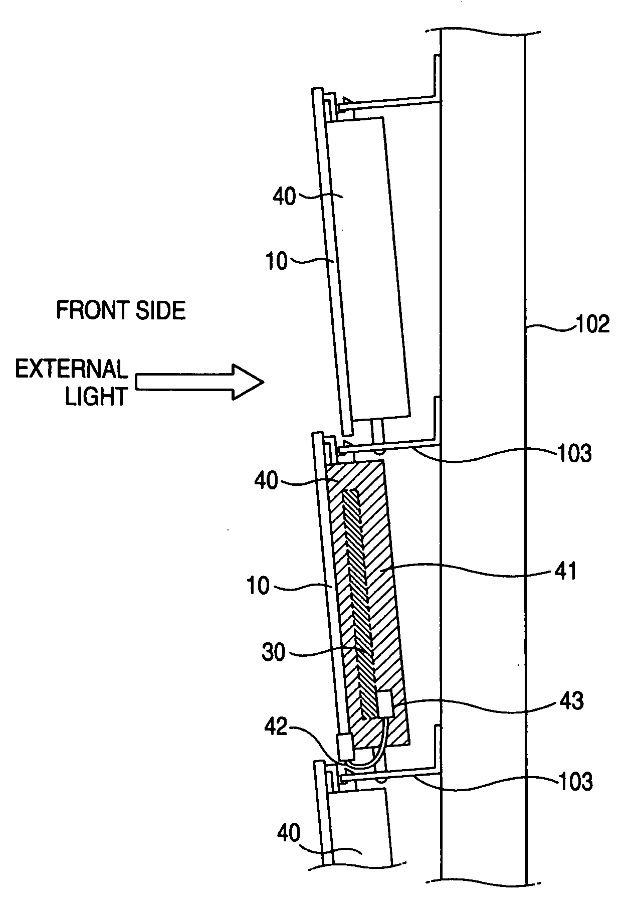
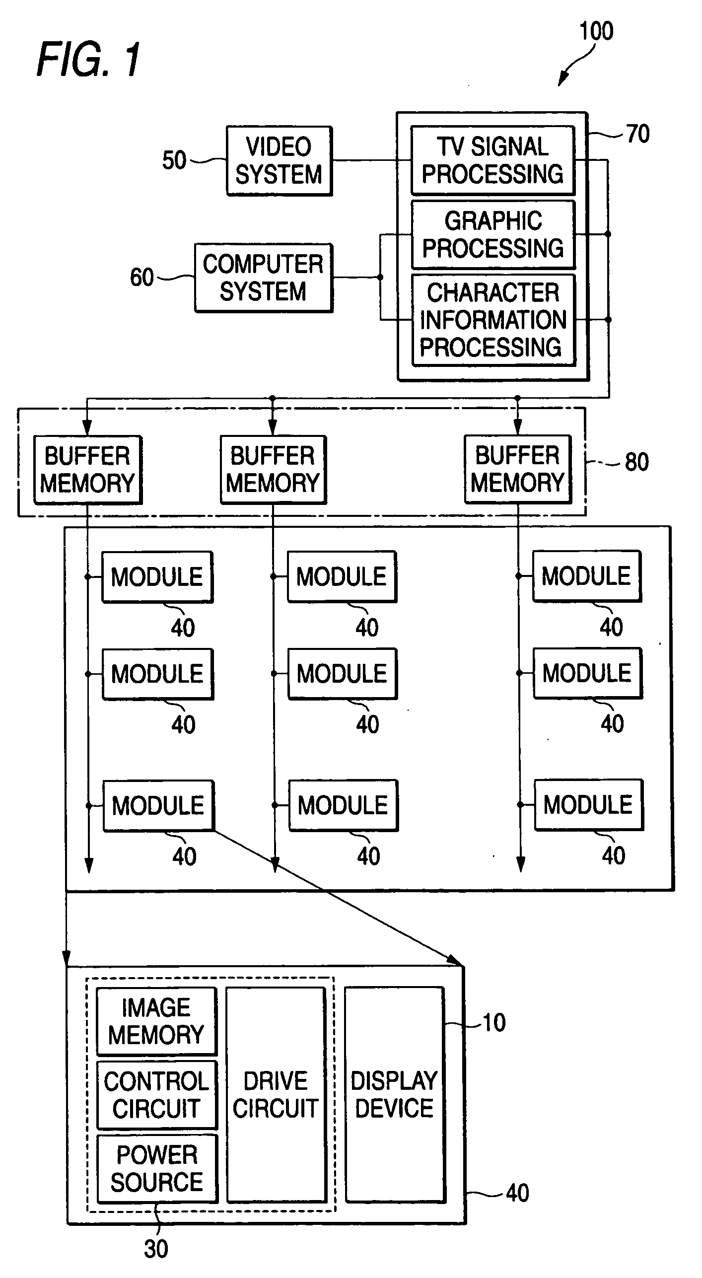
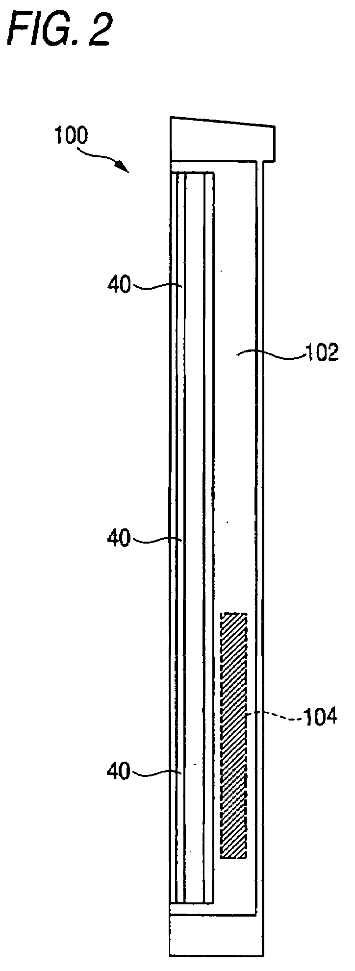
[0027]FIG. 1 is a block diagram showing the typical structure of a large-sized display apparatus of the embodiment 1 of the present invention. The large-sized display apparatus 100 is formed by arranging display modules 40 each of which mounts a control printed circuit board 30 on each display device 10 in a matrix array. Signals to be displayed are supplied from a video system 50 or a computer system 60 and are synthesized by a display controller 70. Further, the synthesized signals are transferred to respective display modules 40 via a buffer memory 80. The display module 40 includes a power source when necessary. To make tile-shaped seams formed among the display devices 10 inconspicuous, the respective display modules 40 are arranged close to each other. On each display module 40, a portion of an image which is divided corresponding to a size of the display module is dis...

embodiment 2

[0039]FIG. 9 is a schematic cross-sectional view of a display device shown in the embodiment 2 of the present invention, wherein the display device uses a reflective display device body 13A as a display device body and adheres a protective glass 20 to a front surface of the reflective display device body 13A using the adhesive material 14.

[0040]The reflective display device body 13A, as shown in FIG. 9, performs a display by reflecting an external light (sunlight at noon and an illumination light at night) and hence, heat is hardly generated whereby it is possible to realize a thin display which exhibits low power consumption and requires no cooling means. Particularly, the display device which uses cholesteric liquid has excellent features such that a display is maintained even when a power source is cut and hence, it is possible to realize the display apparatus of low power consumption.

[0041]On the other hand, the cholesteric liquid crystal may change the display when a mechanical...

embodiment 3

[0042]The glass exhibits high transmissivity of light including ultraviolet rays and hence, a display device such as a liquid crystal panel requires a countermeasure to block the ultraviolet rays. The display device has a front surface (display part) exposed to an external light. A back surface side of the display device faces to the inside of a frame and structural parts such a casing are mounted on the back surface side and hence, the influence of the ultraviolet rays is small and a countermeasure to cope with the ultraviolet rays is applied to the front surface side of the display device.

[0043]FIG. 10 is a schematic cross-sectional view of the display device of the embodiment 3 of the present invention, wherein an adhesive material 14 and an ultraviolet ray blocking film 15 are arranged between a display device body 13 and a protective glass 20. Although the weatherability of the ultraviolet ray blocking film 15 itself is not always high in general, by adhering the protective gla...


PUM


Abstract

A protective measure against rainfalls or ultraviolet rays is applied to planar display devices which comprise a large-sized display apparatus thus allowing display modules which include display devices to be used outdoors and, at the same time, the structure of a frame is simplified thus realizing the reduction of weight, thickness and a manufacturing cost of the large-sized display apparatus. In a large-sized display apparatus arranging a plurality of planar display devices, as the planar display device, a display device which comprises a display device body which includes a display region in the inside thereof and has a peripheral portion of the display region sealed, and a protective glass which is fixedly mounted on a front surface of the display device body using an adhesive material is used.

Description

BACKGROUND OF THE INVENTION[0001]1. Field of the Invention[0002]The present invention relates to a large-sized display apparatus arranging planar display devices, and more particularly to a large-sized display apparatus using outdoors.[0003]2. Description of the Related Art[0004]Heretofore, with respect to this type of large-sized display apparatus, originally, a method which arranges monochroic CRTs (cathode ray tubes) as display devices has been put into practice. Thereafter, a display device which includes a plurality of pixels in the inside of the display device by applying a principle of a CRT or a discharge tube has been developed and the resolution has been remarkably improved. Thereafter, a method which arranges liquid crystal display devices as described in following patent documents 1, 2 has been put into practice. Then, a method which arranges plasma display panels or vacuum fluorescent display has been proposed on a trial basis. In this manner, various types of display d...

Claims


Application Information

Patent Timeline
IPC IPC(8): G02F1/1339
CPCG02F1/13336G02F1/13718G02F2202/28G02F2201/38G02F2201/50G02F2201/086
Inventor HARA, ZENICHIROEGAMI, NORITAKAHIRAKI, MASAAKISAITOU, YUUSAKUITADANI, TAKESHI
Owner TRIVALE TECH
Why Eureka
Try Eureka