Security Devices Incorporating Optically Variable Adhesive

a technology of adhesive and security device, applied in the field of hotstamping, can solve the problems of not providing additional functions, adhesive becomes tacky, and unaffected light passing through,

Active Publication Date: 2007-09-06
VIAVI SOLUTIONS INC
View PDF35 Cites 72 Cited by
  • Summary
  • Abstract
  • Description
  • Claims
  • Application Information

AI Technical Summary

Problems solved by technology

Therefore the goal has been to have an adhesive that “appears” to be as invisible as possible, and substantially matched in refractive index to the substrates with which it is bonding, thereby substantially un-affecting light passing therethrough.
Upon the application of heat, the adhesive becomes tacky in regions of the heated image and adheres to the paper or plastic substrate.
Although these heat-activated adhesives have performed their intended function, they have not provided additional functions now perceived to be highly useful.
The problem is evident often in the hot stamp transfer of the letter “A” where the triangle of the letter “A” is covered with foil.
Furthermore, unfortunately, counterfeiters have at their disposal from the packaging field commercially available transparent film made from hundreds of alternating layers of polymeric films that display similar color shifting and reflection and transmission characteristics as found in '943.
The use of a thin film interference filter has a large drawback in terms of color control because the methods employed, vacuum deposition methods, particularly, those that are of such running speeds to make them commercially viable has at best a plus / minus 2% error on the dielectric layer thickness.
From a practical point of view, this color variation makes the distinction between the genuine product and a counterfeit problematical.
The only hope to improve the color of a foil with a vacuum process is to have extensive editing which only leads to high a high expensive product.
Therefore, the problem that is being addressed is to provide a new security thread with enhanced features that can easily be assembled.

Method used


Image

  • Security Devices Incorporating Optically Variable Adhesive
  • Security Devices Incorporating Optically Variable Adhesive
  • Security Devices Incorporating Optically Variable Adhesive

Examples


Embodiment Construction

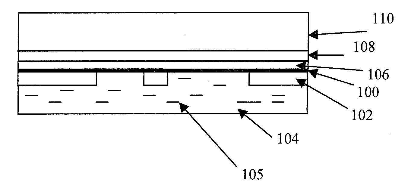
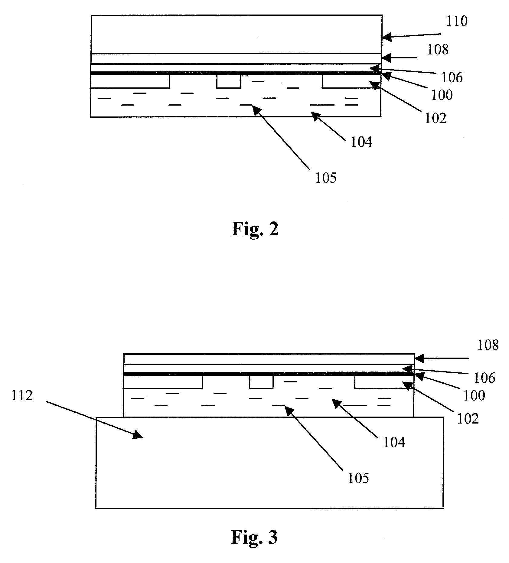
[0066] For the purpose of this application, the term “energy activated adhesive” or “energy activated binder”, means a bonding substance that requires an energy source for curing. The energy activated adhesives include, but are not limited to, hot stamp adhesives, UV activated adhesives, thermoplastic and thermoset adhesives, paint-based polymeric compositions, varnishes, and staining compositions. By way of example, an adhesive is selected from the group of: polymethacrylate, polyacrylate, polyamide, nitrocellulose, alkyd resin, polyvinyl alcohol, polyvinyl acetate, and polyurethane.

[0067] The methods of activating the adhesives include hot stamping, UV curing, applying heat, or a beam of electrons. For brevity, an energy activated adhesive, possibly with special flakes therein, is referred to as “an adhesive” hereinbelow where it does not lead to confusion.

[0068] As was described heretofore, in the background of the invention, the field of hot stamping and more particularly, hot...


PUM

PropertyMeasurementUnit
lengthaaaaaaaaaa
thickaaaaaaaaaa
optical densityaaaaaaaaaa

Abstract

A structure for providing an optical effect comprises a first and second substrates hot stamped together by an adhesive. The adhesive comprises an energy activated binder having a plurality of particles distributed therein or thereon for providing the optical effect detectable through the first substrate.

Description

CROSS-REFERENCE TO RELATED APPLICATION [0001] The present application claims priority from U.S. Provisional Application No. 60 / 744,842 filed on Apr. 14, 2006; U.S. Provisional Application No. 60 / 779,484 filed on Mar. 6, 2006; U.S. Provisional Application No. 60 / 832,826 filed on Jul. 24, 2006; and U.S. Provisional Application No. 60 / 861,608 filed on Nov. 29, 2006. All patents and patent applications mentioned heretofore and hereafter are incorporated herein by reference, for all purposes. [0002] This application is related to U.S. patent application Ser. No. 11 / 273,985 filed Nov. 15, 2005, which is a continuation-in-part application of U.S. patent application Ser. No. 10 / 666,318 filed on Sep. 18, 2003, now U.S. Pat. No. 6,987,590 issued on Jan. 17, 2006 entitled “Patterned Reflective Optical Structures”; U.S. Provisional Application No. 60 / 673,080 filed on Apr. 20, 2005 entitled “Patterned Reflective Optical Structures”; and U.S. Provisional Application No. 60 / 729,907 filed Oct. 25, ...

Claims


Application Information

Patent Timeline
Patent Type & Authority Applications(United States)
IPC IPC(8): G03H1/00
CPCB42D2033/20B42D25/00C09J11/02D21H21/40D21H21/44D21H21/48G02B5/285G03H1/0011G03H1/0244G03H1/26G03H2001/0016G03H2001/188G03H2210/55G03H2270/12G03H2270/24B42D2035/24B42D25/324B42D25/328B42D25/378B42D25/373B42D25/47B41M3/14B41M5/00G03H1/0005
Inventor PHILLIPS, ROGER W.MAYER, THOMASLAMAR, SCOTTTEITELBAUM, NEIL
Owner VIAVI SOLUTIONS INC
Why Eureka
Try Eureka