Magnetic head drive circuit

a head drive circuit and head drive technology, applied in the direction of h-bridge head driver circuit, data recording, instruments, etc., can solve the problem of deleting information in neighboring tracks, and achieve the effect of reducing circuit area, improving writing performance, and maintaining uniformity of circuit elements

Inactive Publication Date: 2007-09-06
ROHM CO LTD
View PDF12 Cites 10 Cited by
  • Summary
  • Abstract
  • Description
  • Claims
  • Application Information

AI Technical Summary

Benefits of technology

[0021]The abovementioned magnetic head drive circuit may be integrated on one semiconductor substrate. “Integrated” includes cases in which all component elements of the circuit are formed on the semiconductor substrate, and cases in which main component elements of the circuit are integrated, and some resistors, capacitors, or the like, for adjusting a circuit constant may be arranged outside the semiconductor substrate. By integrating the magnetic head ...

Problems solved by technology

Here, there is a tendency for the writing capability to improve with a larger overshoot amount, but if ...

Method used


Image

  • Magnetic head drive circuit
  • Magnetic head drive circuit
  • Magnetic head drive circuit

Examples


first embodiment

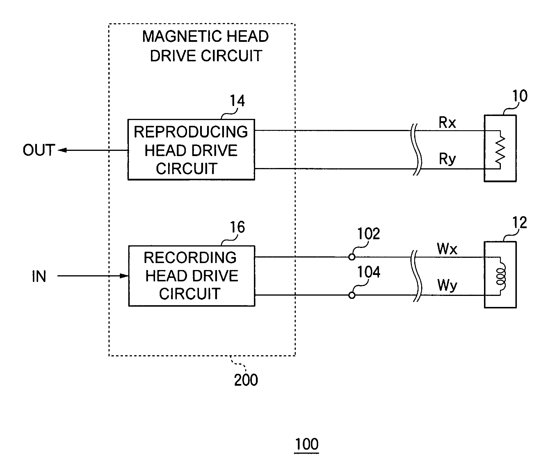
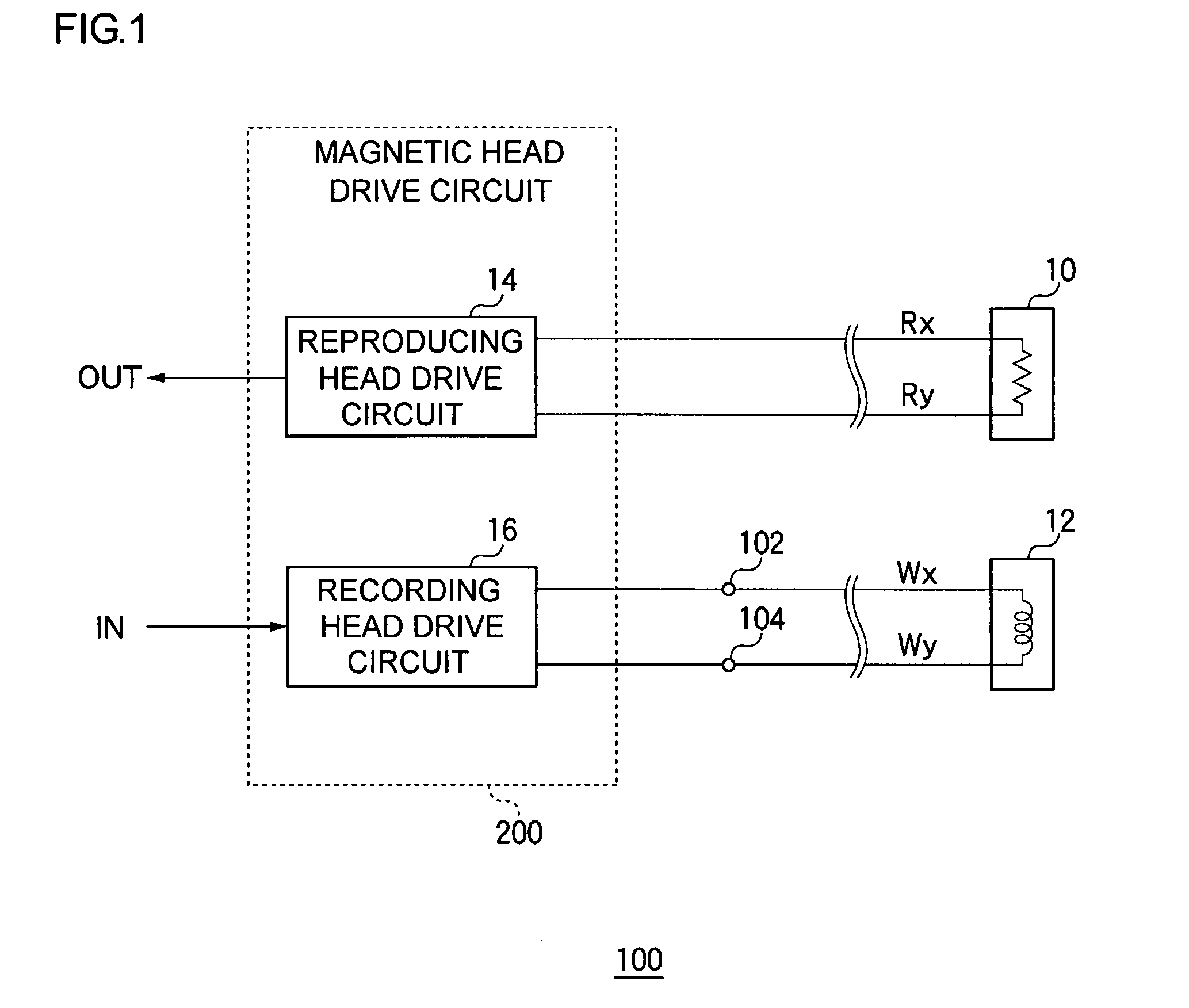
[0051]FIG. 1 is a circuit diagram showing a configuration of a magnetic recording and reproducing apparatus 100 according to a first embodiment. This magnetic recording and reproducing apparatus 100 is a hard disk device for writing information to, or reading information from, a magnetic disk not shown in the figure, and includes a reproducing head 10, a recording head 12, and a magnetic head drive circuit 200.

[0052]In this magnetic recording and reproducing apparatus 100, a coil is installed in the recording head 12, and is disposed adjacent to the magnetic disk that rotates at a high speed. When a signal current, corresponding to information that is to be recorded, flows, an induction field is generated in the coil of the recording head 12, the magnetic disk is magnetized by a magnetic flux that escapes from a magnetic gap, and the information is written.

[0053]The reproducing head 10 includes an MR element in which a resistance value changes according to magnetic flux, and since t...

second embodiment

[0093]In general, since the overshoot time period Tos is normally extremely short, being a few hundred ps, the current flowing in each of the transistors 22, 24, 31, 32, and 44 deviates from a current value determined by a mirror ratio of the current mirror circuit. As a result, under a certain condition, cases are envisaged in which the overshoot amount of the write current Iw cannot be adequately controlled in the circuit according to the first embodiment. The second embodiment explained below is combined with technology explained in the first embodiment, or is used alone, and relates to technology for accurately controlling overshooting of the write current Iw.

[0094]FIG. 6 is a circuit diagram showing part of a configuration of the recording head drive circuit 16a according to the second embodiment. The recording head drive circuit 16a according to the second embodiment is distinguished in that a clamp circuit 60 is provided.

[0095]The clamp circuit 60 performs clamping such that ...

third embodiment

[0103]The second embodiment focuses on behavior when the voltage Vx and Vy of the two terminals of the recording head 12 swing in a ground (or negative supply voltage) direction, and an explanation was given concerning technology for controlling the overshoot amount. Compared with this, the third embodiment explained below focuses on behavior when the voltage Vx and Vy of the two terminals of the recording head 12 swing in a supply voltage Vdd direction, and concerns controlling the overshoot amount.

[0104]FIG. 9 is a circuit diagram showing a configuration of a recording head drive circuit 16b according to the third embodiment. A pull-up circuit 70, during an overshoot time period Tos, pulls up the voltages Vx and Vy of the two terminals of the recording head 12 independently to a predetermined pull-up level. Below, the write current Iw flowing in the recording head 12 has a first direction when flowing from the first terminal 102 to the second terminal 104, and has a second directi...


PUM


Abstract

A recording head drive circuit drives a recording head that records information on a magnetic recording medium. A switching circuit is a H-bridge circuit which includes a plurality of transistors. The switching circuit switches direction of a write current (Iw) flowing in the recording head, in accordance with a conduction state of each transistor. A write current controller controls the write current (Iw) in the recording head. An overshoot control circuit adds an overshoot current (Ios), proportional to the write current (Iw), to the write current (Iw) flowing in the recording head, in a predetermined overshoot time period.

Description

BACKGROUND OF THE INVENTION[0001]1. Field of the Invention[0002]The present invention relates to a magnetic recording and reproducing apparatus for recording data on, and reproducing data from, magnetic recording media, and in particular, to technology for controlling overshoot electrical current added to write current when recording data.[0003]2. Description of the Related Art[0004]Magnetic recording and reproducing apparatuses represented by hard disks are much used as recording media that are used inside electronic devices of recent years. In such magnetic recording and reproducing apparatuses, a current (referred to below as a write current) flowing in a coil of a write magnetic head (recording head) is controlled in order to record magnetically recorded data. To drive the magnetic head, a magnetic head drive circuit including a switching circuit, such as a H-bridge circuit or the like, is used.[0005]The magnetic head drive circuit controls direction of the write current flowing...

Claims


Application Information

Patent Timeline
IPC IPC(8): G11B5/09G11B15/12G11B5/02
CPCG11B5/02G11B2005/0018G11B5/022
Inventor HOKUTO, SHINGO
Owner ROHM CO LTD
Why Eureka
Try Eureka