Optofluidic microscope device

a microscope device and fluorescence technology, applied in the field of microfluidics, can solve the problems of significant technical barriers to using nsoms, inability to easily image bacteria with conventional optical microscopy, and difficulty in performing high throughput imaging with an nsom, etc., to achieve high throughput imaging capability, high processing speed, and high throughput imaging rate

Inactive Publication Date: 2007-09-06
CALIFORNIA INST OF TECH
View PDF9 Cites 99 Cited by
  • Summary
  • Abstract
  • Description
  • Claims
  • Application Information

AI Technical Summary

Benefits of technology

[0011] The high speed processing capability of embodiments of the invention and the ability to use multiple optofluidic microscope devices in embodiments of the invention allow embodiments of the invention to have substantially higher imaging throughput rates than NSOMs. For example, in an NSOM device, the acquisition time for a 100×100 pixel image is about 10 milliseconds. In comparison, a parallel series of 10 optofluidic microscope devices built on a single 1000 pixel linear CCD array can provide up to one hundred 100×100 pixel images in the time that an NSOM creates a single image. The high throughput imaging capability and high resolution of the optofluidic microscope devices according to embodiments of the invention make them highly suited for various clinical applications. Such applications include differentiating between different bacteria types.
[0012] Also, the optofluidic microscope devices according to embodiments of the invention eliminate the bulky optics (e.g., sets of objective lenses and complex microscope setups) that are used to obtain biological images in conventional microfluidic devices. Unlike conventional imaging systems, the optofluidic microscope devices according to embodiments of the invention are portable and compact.

Problems solved by technology

NSOMs are especially useful for profiling bacteria, because bacteria cannot be easily imaged with conventional optical microscopy.
However, the lack of publications on this suggests that significant technical barriers exist to using NSOMs.
One such barrier is the difficulty of performing high throughput imaging with an NSOM.

Method used


Image

  • Optofluidic microscope device
  • Optofluidic microscope device
  • Optofluidic microscope device

Examples


Embodiment Construction

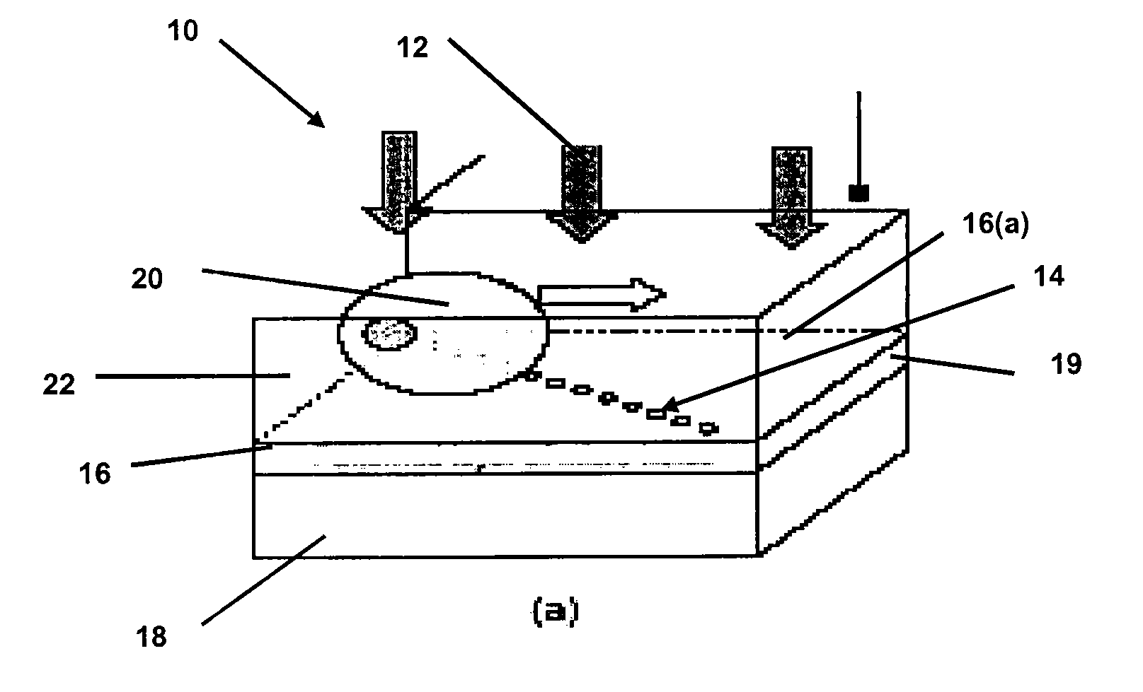
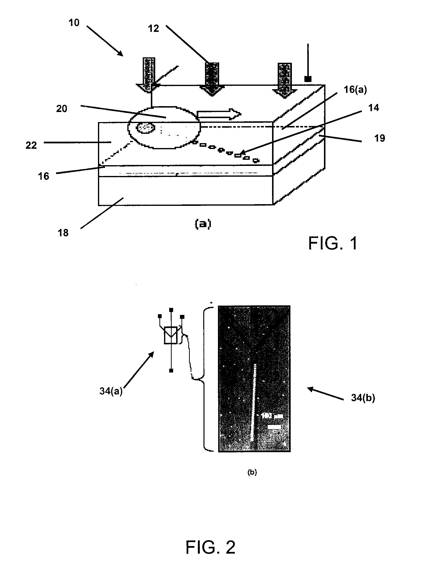
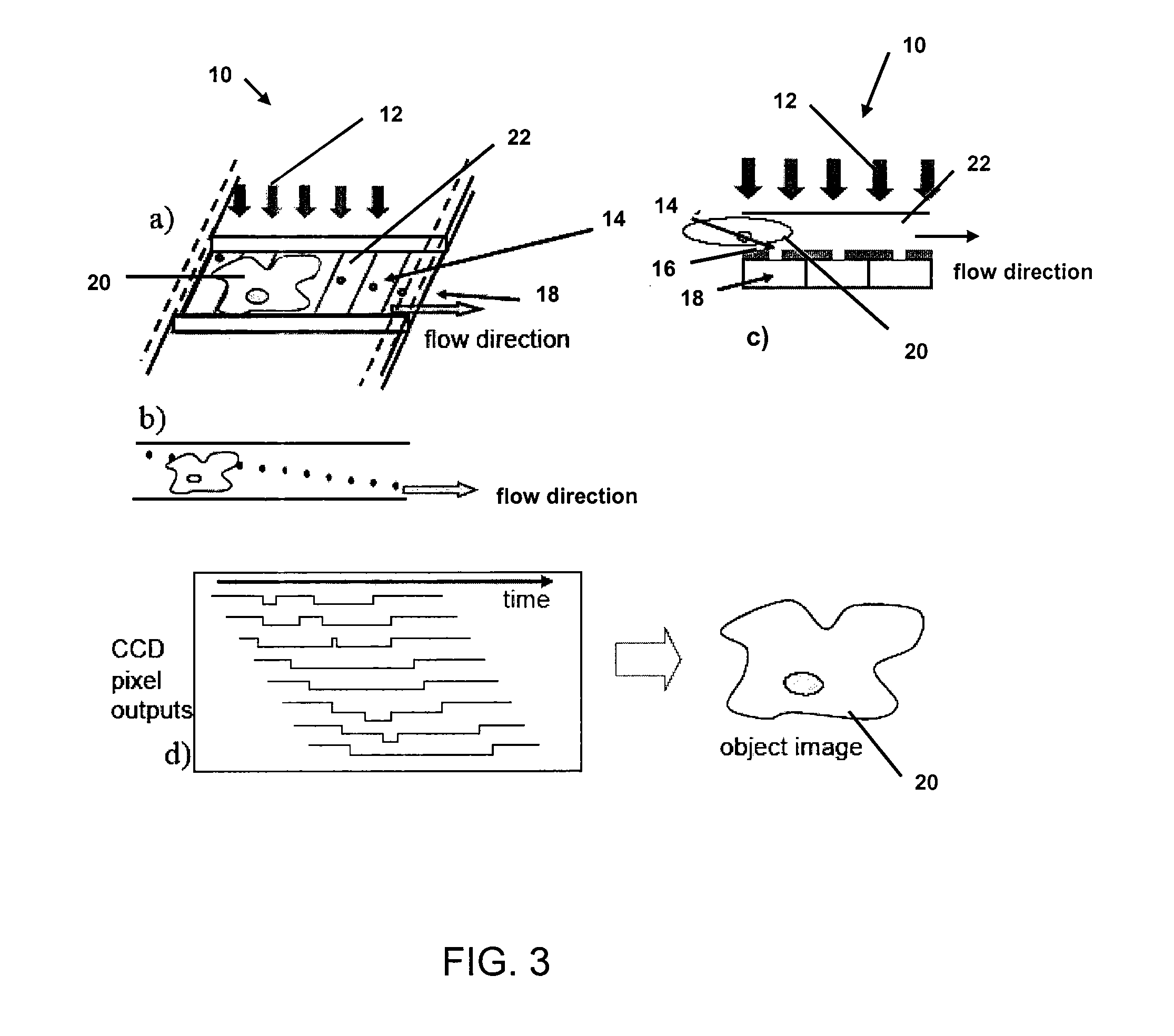
[0047] Embodiments of the invention are directed to optofluidic microscopes that can use light transmissive regions (e.g., spaced holes) or discrete light emitting elements (e.g., quantum dots) in a body defining at least a portion of a fluid channel. The light transmissive regions or the light emitting elements (in conjunction with other elements) can be used to image entities such as biological entities passing through the fluidic channel. Other embodiments are directed to optofluidic microscope devices that have at least one light imaging element in or on a surface of a bottom wall defining a fluid channel. The light imaging elements may be in the form of one or more light transmissive regions such as holes, one or more light emitting elements such as quantum dots, one or more linear structures such as reflective lines or lines of closely adjacent quantum dots, or even one or more light scattering bodies such as nanoparticles.

[0048] In the specifically described embodiments, the...


PUM

PropertyMeasurementUnit
widthaaaaaaaaaa
widthaaaaaaaaaa
diameteraaaaaaaaaa

Abstract

An optofluidic microscope device is disclosed. The device includes a fluid channel having a surface and an object such as a bacterium or virus may flow through the fluid channel. Light transmissive regions of different sizes may be used to image the object.

Description

CROSS-REFERENCES TO RELATED APPLICATIONS [0001] This application is a continuation-in-part application of U.S. patent application Ser. No. 11 / 125,718, filed on May 9, 2005, which is a non-provisional of and claims priority to U.S. provisional patent application Nos. 60 / 590,768, filed on Jul. 23, 2004, and 60 / 577,433, filed on Jun. 4, 2004. This application is also a non-provisional of, and claims the benefit of the filing date of U.S. provisional patent application No. 60 / 783,920, filed on Mar. 20, 2006. All of these applications are herein incorporated by reference in their entirety for all purposes.STATEMENT AS TO RIGHTS TO INVENTIONS MADE UNDER FEDERALLY SPONSORED RESEARCH OR DEVELOPMENT [0002] NOT APPLICABLE BACKGROUND OF THE INVENTION [0003] The field of microfluidics has advanced rapidly. These advancements relate to the development of large-scale integration of microfluidic circuits, and numerous applications of microfluidics to life science research. Currently, optical micro...

Claims


Application Information

Patent Timeline
Patent Type & Authority Applications(United States)
IPC IPC(8): G01N21/00B32B27/04
CPCG01N21/6458B82Y30/00
Inventor YANG, CHANGHUEIPSALTIS, DEMETRI
Owner CALIFORNIA INST OF TECH
Why Eureka
Try Eureka