High-density orthogonal connector

a connector and high-density technology, applied in the direction of coupling device connection, coupling contact member, coupling device details, etc., can solve the problems of signal skew, right-angle connectors may exhibit undesirable level of signal skew, and signal skew may be problematic, so as to reduce insertion loss, reduce weight, and constant impedance

Active Publication Date: 2007-09-06
FCI AMERICAS TECH LLC
View PDF50 Cites 94 Cited by
  • Summary
  • Abstract
  • Description
  • Claims
  • Application Information

AI Technical Summary

Benefits of technology

[0015] The orthogonal connector may also include novel contact configurations for reducing insertion loss and maintaining substantially constant impedance along the lengths of contacts. The use of air as the primary dielectric to insulate the contacts may result in a lower weight connector that is suitable for use in various connectors, such as a right angle ball grid array connector or a mezzanine BGA connector. Plastic or other suitable dielectric material may be used. The connector is preferably devoid of internal and external shields, but shields may also be added. Crosstalk should be in to a range of about six percent or less a signal rise times of about 200 to 35 picoseconds. The connector also preferably has an impedance of 100±10 Ohms or 85±10 Ohms.

Problems solved by technology

This may cause the end-to-end propagation time of each electrical contact to vary, thereby resulting in signal skew.
Signal skew may be problematic for applications that rely on differential signals, for example.
Thus, right-angle connectors may exhibit an undesirable level of signal skew and may be unsuitable for applications that utilize differential signals, for example.

Method used


Image

  • High-density orthogonal connector
  • High-density orthogonal connector
  • High-density orthogonal connector

Examples


Embodiment Construction

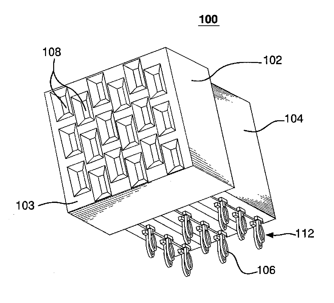
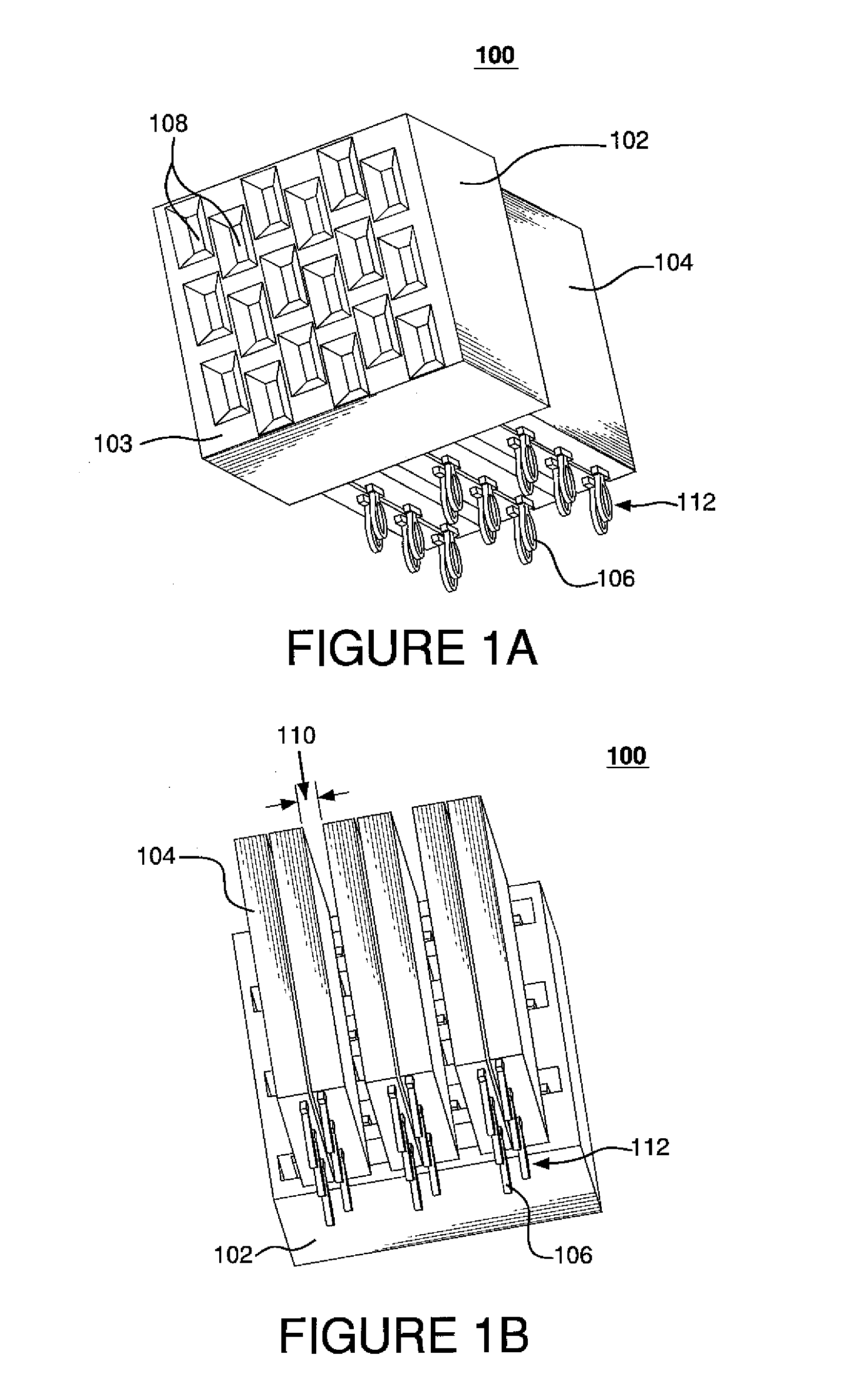
[0029]FIGS. 1A and 1B depict perspective views of high-density orthogonal connector 100 having electrical contacts 112, mating interface housing 102 and one or more lead portion housings 104. Connector 100 may be a female, or receptacle, connector. Connector 100 may be a right-angle connector and may be implemented in either orthogonal or non-orthogonal printed circuit board (PCB) applications. Connector 100 may also be a mezzanine connector or a header connector. Connector 100 may be devoid of any electrical shielding and / or ground contacts.

[0030] Face 103 of mating interface housing 102 may define a receptacle interface, with multiple slots 108 for receiving electrical contacts on a mating connector (not shown in FIGS. 1A and 1B). Slots 108 may be arranged in columns. Each adjacent column of slots 108 may be offset from one another in the direction of the column. The backside of receptacle housing 102 may interface with one or more lead portion housings 104, which may be separate...


PUM


Abstract

A high-density orthogonal connector is disclosed and may include electrical contacts that are configured to receive contacts from an orthogonal header connector while minimizing signal skew and signal reflection. The electrical contacts in the connector may define contact pairs (e.g., differential signal pairs). Each contact pair may include a lead portion and a mating interface that extends from the lead portion. The lead portions of the contact pair may define a first plane. One contact of the contact pair defines a first mating interface defining a second plane and the other contact in the contact pair defines a second mating interface defining a third plane. The second plane and the third plane may be both substantially parallel to and offset from the first plane in opposite directions. The contact pair may be configured such that the overall length of each contact within the pair may be substantially the same.

Description

CROSS REFERENCE TO RELATED APPLICATIONS [0001] The present application is related by subject matter to U.S. Patent Application Serial No. (not assigned) (Attorney Docket No. FCI-2977) filed on Mar. 3, 2006 and titled “Edge and Broadside Coupled Connector,” U.S. Patent Application Serial No. (not assigned) (Attorney Docket No. FCI-2979) filed on Mar. 3, 2006 and titled “Electrical Connectors,” and U.S. Patent Application Serial No. (not assigned) (Attorney Docket No. FCI-2953) filed on Mar. 3, 2006 and titled “Broadside-to-Edge-Coupling Connector System,” the contents of each of which are hereby incorporated by reference in their entireties.FIELD OF THE INVENTION [0002] Generally, the invention relates to orthogonal connectors. More particularly, the invention relates to high-density orthogonal connectors having pairs of electrical contacts that have minimal signal skew and a substantially constant differential impedance profile that may be matched to a system impedance. BACKGROUND O...

Claims


Application Information

Patent Timeline
Patent Type & Authority Applications(United States)
IPC IPC(8): H01R12/00
CPCH01R23/688H01R13/6587H01R12/00
Inventor MINICH, STEVEN E.
Owner FCI AMERICAS TECH LLC
Why Eureka
Try Eureka