Blood pressure measurement

Inactive Publication Date: 2007-09-06
WELCH ALLYN INC
View PDF12 Cites 4 Cited by
  • Summary
  • Abstract
  • Description
  • Claims
  • Application Information

AI Technical Summary

Problems solved by technology

Although such conventional prior art automatic blood pressure monitoring devices are effective, components such as pressure transducers and analog-to-digital converters are costly and complicate the devices.

Method used


Image

  • Blood pressure measurement
  • Blood pressure measurement
  • Blood pressure measurement

Examples


Embodiment Construction

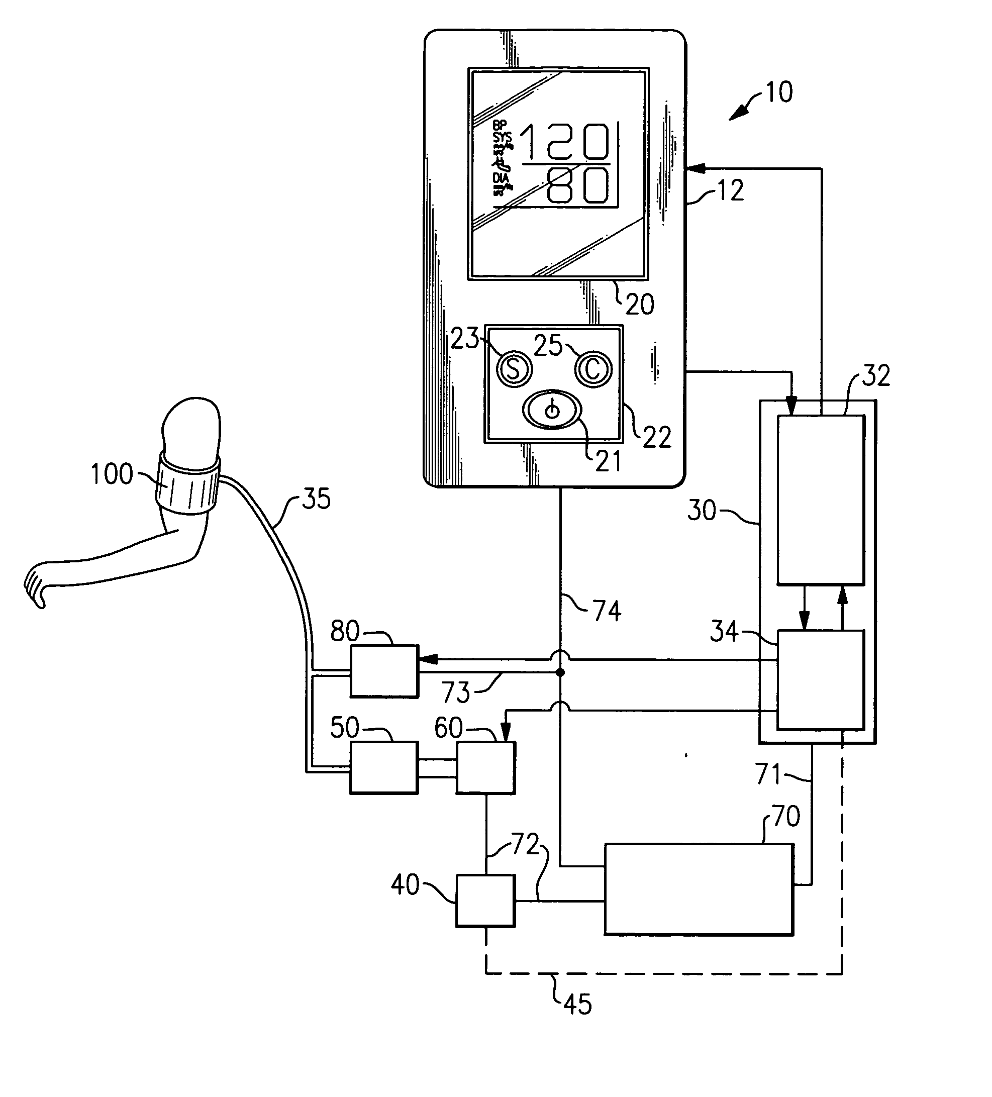
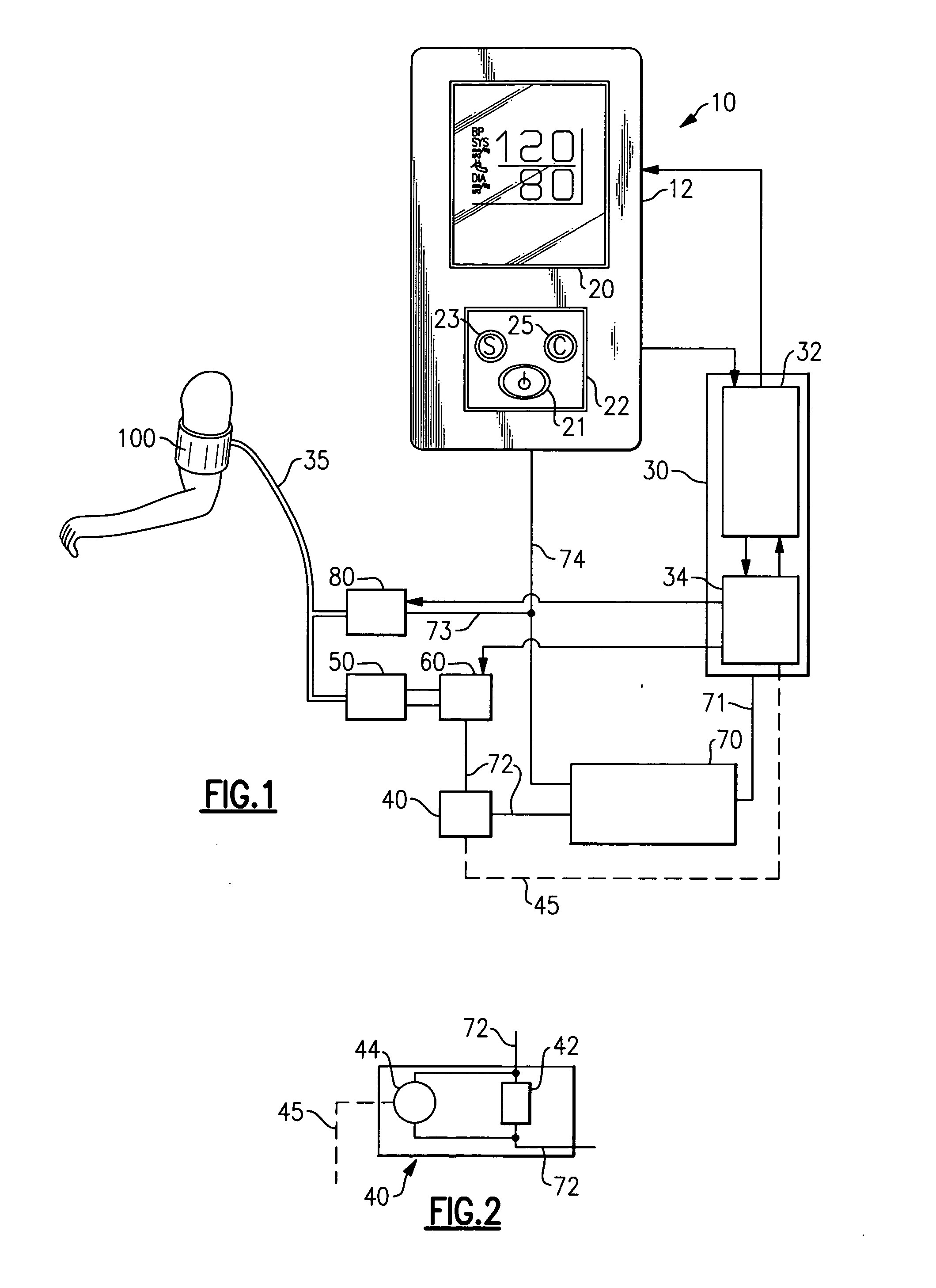
[0018] The present invention will be described herein with reference to an exemplary embodiment of a modular blood pressure measurement apparatus 10 depicted in FIG. 1. In the depicted embodiment, the blood pressure measurement apparatus 10 includes a display 20 and a user interface 22 operatively connected to a controller 30 that includes a central processing unit, “CPU”, 32 and non-invasive blood pressure module, “NIBP”, 34. The blood pressure measurement apparatus 10 further includes an air pump 50, a direct current motor 60, a power supply 70, such as rechargeable battery power pack, and a vent valve 80. The power supply 70 supplies power to the controller 30 through line 71, to the DC motor 60 through line 72, to the vent valve 80 through line 73 and to the display 20 and user interface 22 through line 74. The pump 50 and vent valve 80 are coupled in pneumatic communication in a conventional manner via a flexible conduit 35 to a blood pressure measurement cuff 100 applied to a ...


PUM


Abstract

In blood pressure measurement of a vertebrate through use of an inflatable pressure cuff disposed about a limb of the vertebrate limb and inflated by pump driven by a motor, the air pressure within the cuff is determined at any given time during the inflation of the cuff by calculating the incremental change in pressure in the pressure cuff over a series of small time increments and summing the calculated incremental pressure changes from the initiation of cuff inflation to a desired point in time during the inflation of the pressure cuff. The incremental change in pressure within the cuff is calculated as a function of the incremental change in current drawn by the pump motor over the time increment.

Description

FIELD OF THE INVENTION [0001] This invention relates generally to the non-invasive measurement of blood pressure and, more particularly, to the measurement of blood pressure via a blood pressure apparatus equipped with a rotary pump. BACKGROUND OF THE INVENTION [0002] The measurement of blood pressure is a common procedure used in hospitals, clinics and physicians' offices as a tool to assist in diagnosis of illness and monitoring of sick patients, as well as an indicator of the general status of a person's health. In standard non-invasive blood pressure measurement practice, blood pressure is measured using an inflatable sleeve, commonly referred to as a cuff, to measure arterial blood pressure. The cuff, which is adapted to fit around a limb over an artery of a patient, typically around the patient's arm over the brachial artery, includes an interior chamber adapted to be inflated with air to provide a certain amount of pressure on the artery in the arm. [0003] Electronic blood pr...

Claims


Application Information

Patent Timeline
IPC IPC(8): A61B5/02
CPCA61B5/021
Inventor WHITAKER, TYSON B.MEYERSON, CRAIG M.WRIGHT, EDWARDPINGEL, MARK E.
Owner WELCH ALLYN INC
Why Eureka
Try Eureka