Surgical device

a surgical device and joy stick technology, applied in the field of surgical devices, can solve the problems of requiring a lot of skill in the operation of the joy stick, and achieve the effect of simple structure, easy operation, and no skill requiremen

Inactive Publication Date: 2007-09-06
HITACHI LTD
View PDF2 Cites 963 Cited by
  • Summary
  • Abstract
  • Description
  • Claims
  • Application Information

AI Technical Summary

Benefits of technology

[0023] In accordance with the-present invention, since the position and the attitude of the grip portion serving as the forceps execute a dummy motion to the operation of the operator in the operation portion apart from the forceps without using any electronic control of an actuator or the like, it is possible to remote control the motion of the-grip portion on the basis of a visceral operation without requiring a lot of skill.
[0024] Further, it is possible to provide a surgical device which has a simple structure and is easily operated.

Problems solved by technology

However, in the prior art shown in the patent document 1, since the rotational operations of the first rotational shaft and the second rotational shaft provided in the joint portion execute positioning and attitude determination of the forceps by applying complex lateral and vertical operations to a joy stick provided in the operation rod, and the positioning and the attitude determination are executed by driving a motor installed in the operation rod, it is necessary to execute a complex control on the basis of the operation of the joy stick and the drive of the motor.
Further, in the patent document 2, the drive wire is directly operated by the manually operated joy stick without using the motor, however, the operation of the joy stick requires a lot of skill at a time of appropriately setting the position and the attitude of the treatment portion.

Method used


Image

  • Surgical device
  • Surgical device
  • Surgical device

Examples


Embodiment Construction

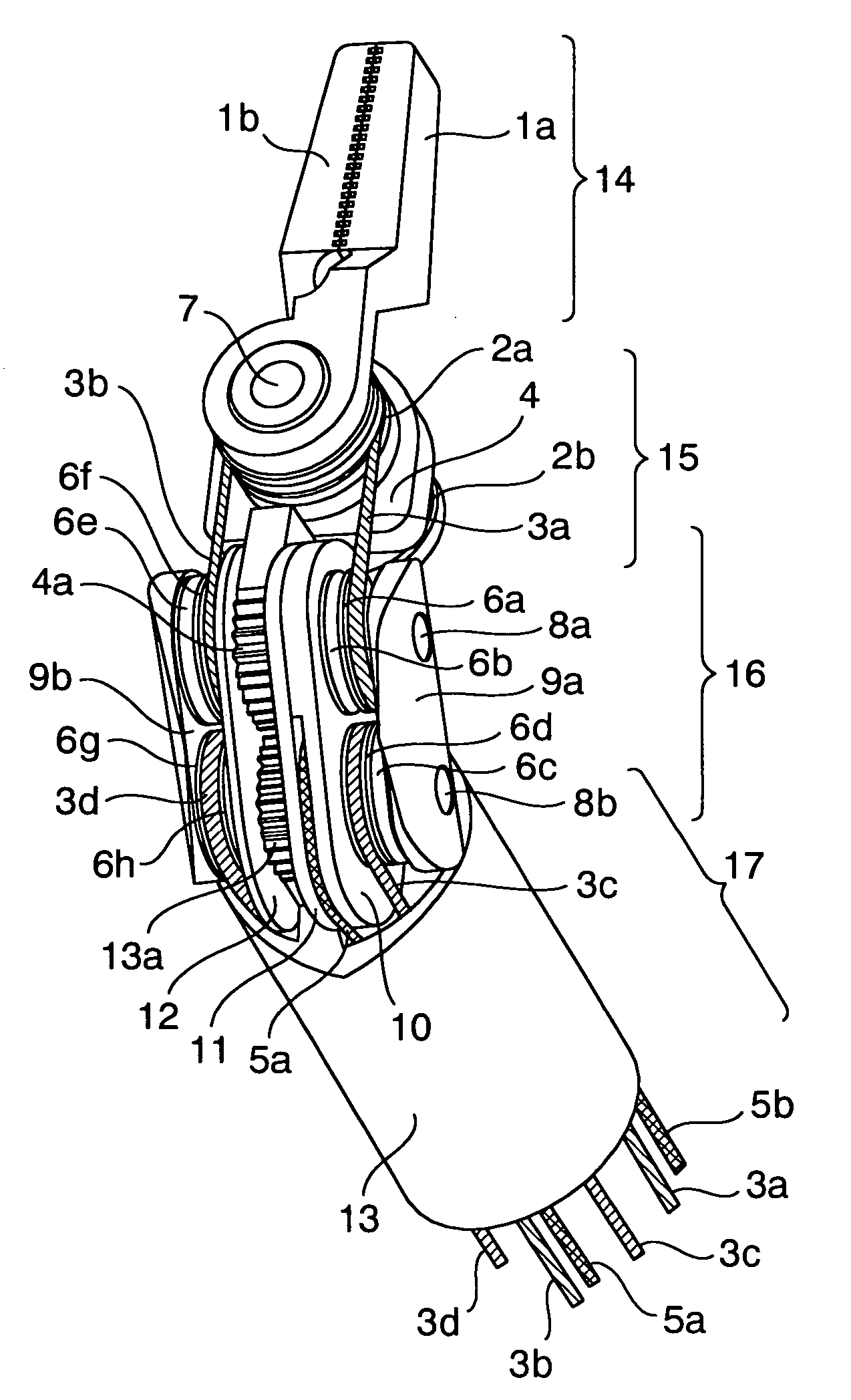
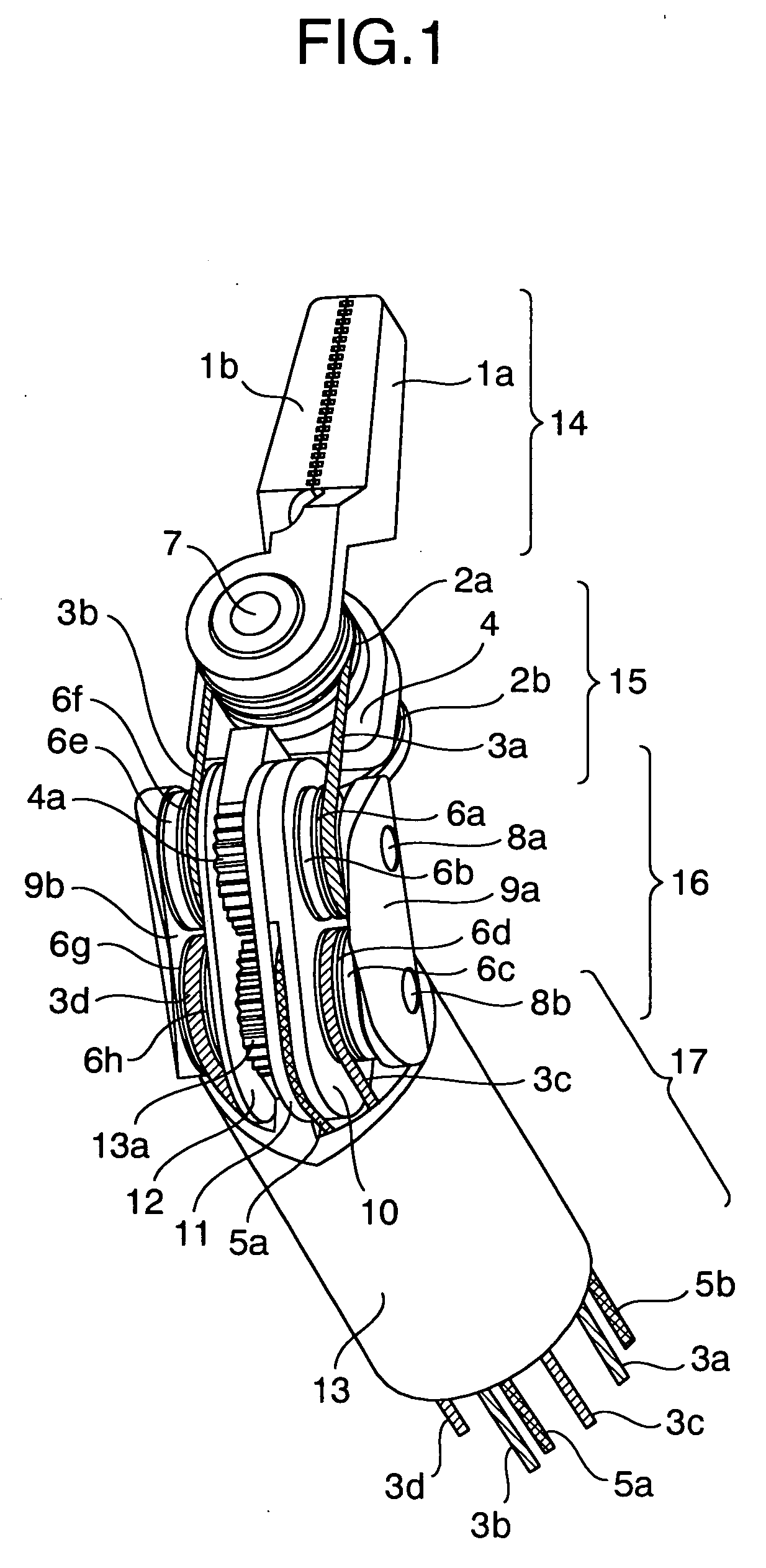
[0042] A description will be in detail given below of a surgical device in accordance with an embodiment of the present invention with reference to the accompanying drawings. First, a description will be given of a basic structure of a surgical device in accordance with the embodiment of the present invention with reference to FIGS. 1 to 4.

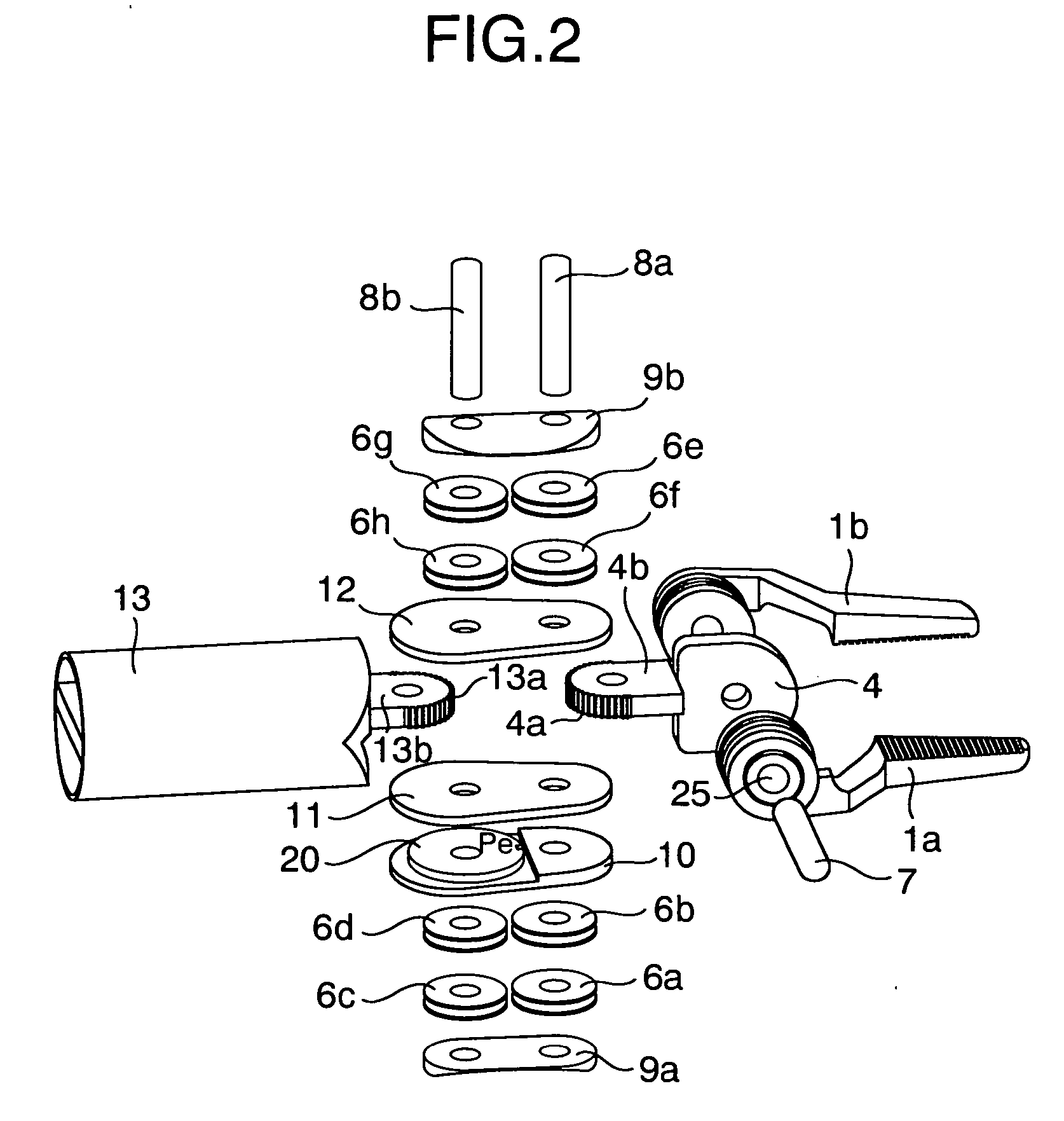
[0043]FIG. 1 is a perspective view of a leading end portion in a surgical device in accordance with the present embodiment. FIG. 2 is an exploded perspective view of a leading end portion of the surgical device shown in FIG. 1. In FIG. 2, in order to easily understand, a blade and a wire driving a swing of a joint are omitted. FIG. 3 is a view explaining a wiring state of the wire and shows a state in which the joint is straight and a state in which the joint is bent. FIG. 4 is a detailed perspective view of a leading end portion in the surgical device in accordance with the present embodiment.

[0044] In the present embodiment, for a particular d...


PUM


Abstract

The invention provides a surgical device which can control a position and an attitude of a multi degree of freedom type grip portion (forceps) in a dummy manner on the basis of an operation of an operator in an operating portion. In a surgical device provided with a leading end joint portion having a leading end grip portion, a near-side joint portion having an operation portion, a handle portion supporting the operation portion, and an arm portion storing a wire for linking motions of the leading end joint portion and the near-side joint portion, the leading end joint portion is moved downward and upward by operating the operation portion and the handle portion upward and downward around the near-side joint portion, and the leading end joint portion is moved rightward and leftward by operating the operation portion and the handle portion leftward and rightward, thereby making the leading end joint portion execute a swing motion, and the leading end grip portion is opened and closed by opening and closing finger rests of the operation portion.

Description

BACKGROUND OF THE INVENTION [0001] 1. Field of the Invention [0002] The present invention relates to a surgical device used in a clinical field, and more particularly to a surgical device which can apply a dummy operation to multi degrees of freedom type forceps a position and an attitude of which are operated by a wire driving type joint portion. [0003] 2. Description of Related Art [0004] As a prior art of a medical manipulator which has a movable portion having two degrees of freedom in a leading end of the forceps, and has a forceps operating portion in a rear end portion of the forceps so as to finely operated the forceps, as shown in patent document 1 (JP-A-2001-276091), there is a structure in which a first rotational joint and a second rotational joint are provided in the leading end of the forceps, a positioning operation of a leading end of the forceps is executed by controlling respective rotational joints via a wire, a gear or the like on the basis of a motor drive in an...

Claims


Application Information

Patent Timeline
Patent Type & Authority Applications(United States)
IPC IPC(8): A61B17/00
CPCA61B17/29A61B17/2909A61B19/22A61B2017/00424A61B2017/00438A61B2019/2246A61B2017/2925A61B2017/2927A61B2017/2939A61B2019/2242A61B2017/291A61B2034/715A61B34/70A61B34/71
Inventor NISHIZAWA, KOUJIHOSHINO, TAKESHIMARUYAMA, YUKINOBU
Owner HITACHI LTD
Why Eureka
Try Eureka