

Power Transmission Apparatus for Working Vehicle
- Summary
- Abstract
- Description
- Claims
- Application Information
AI Technical Summary
Benefits of technology
Problems solved by technology
Method used
Image

Examples
Embodiment Construction
[0063]Power transmission units A1 to A4, B, C1, C2, D and E, serving as embodiments of a unified power transmission apparatus (hereinafter, referred to as a “power transmission unit”) according to the present invention, will be described.
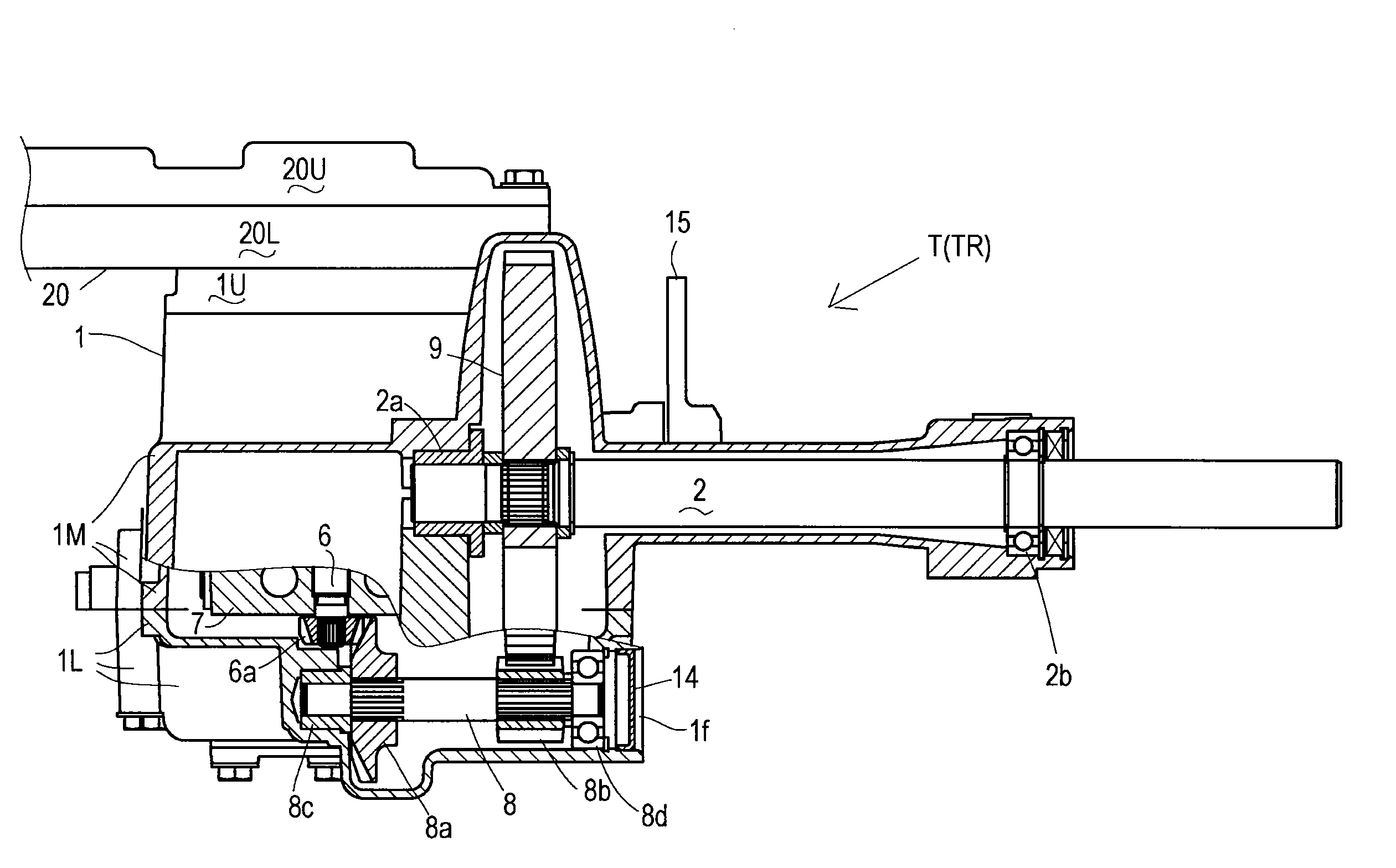
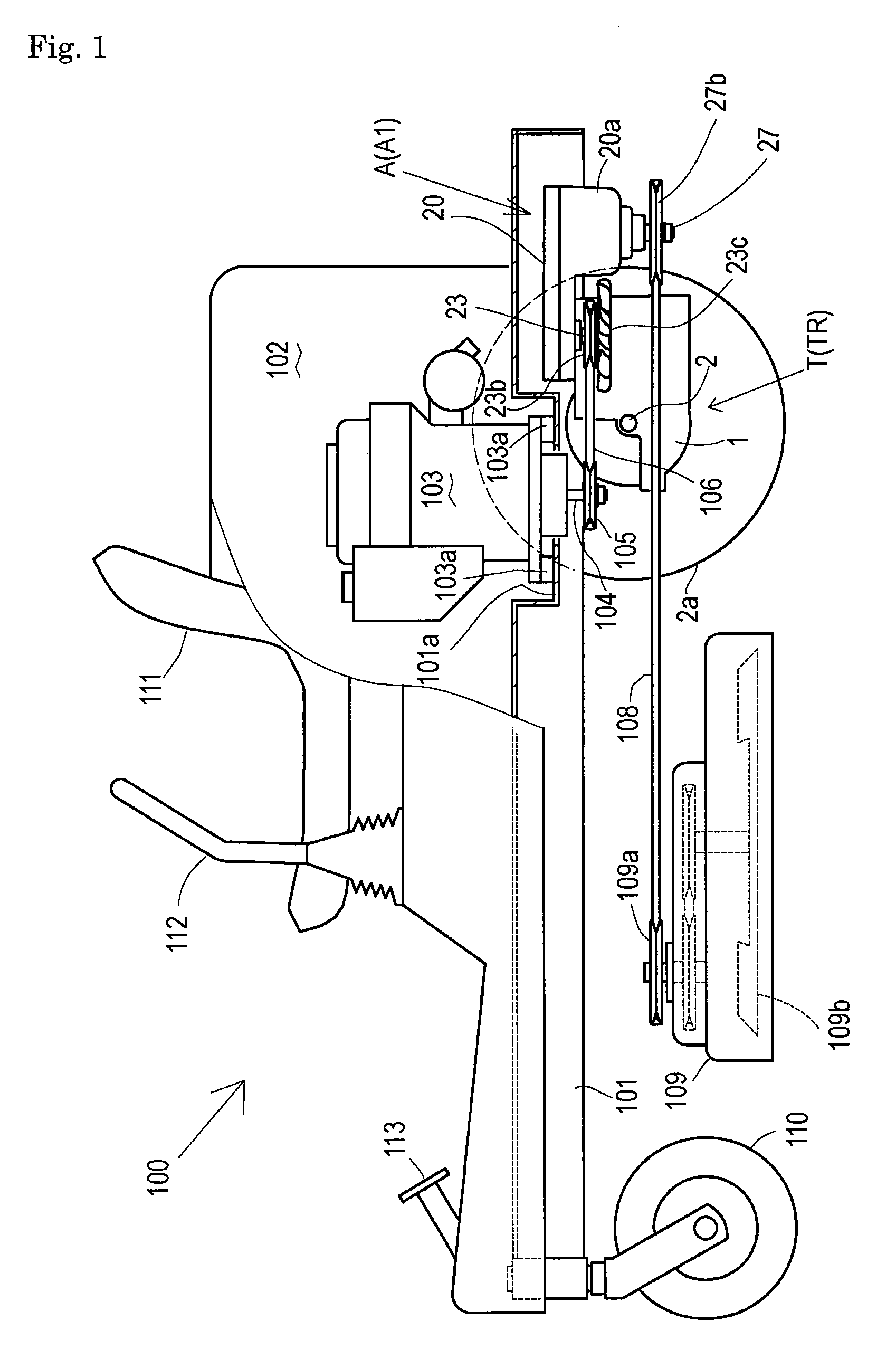
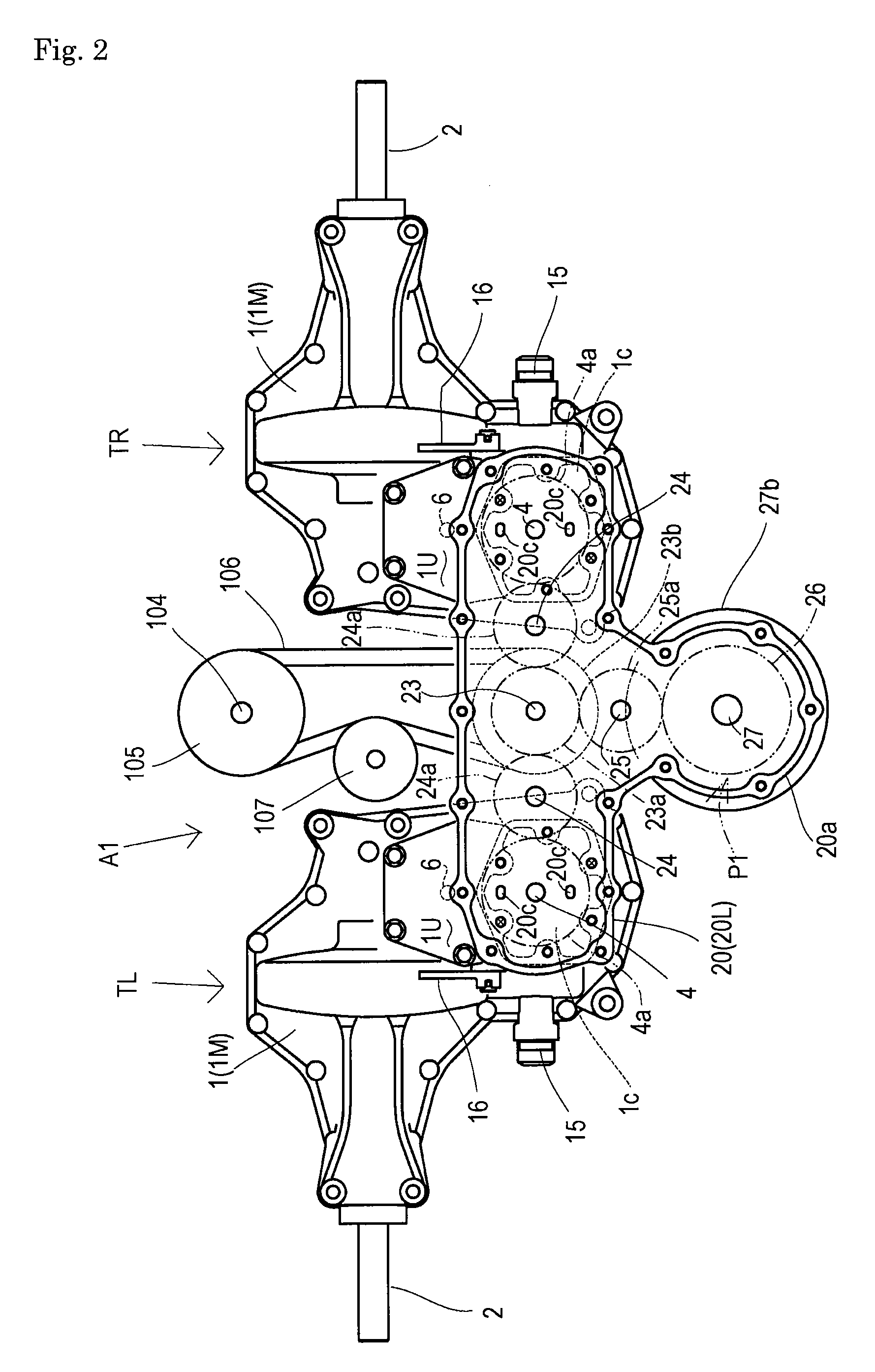
[0064]In a common structure shared among all these power transmission units, a pair of left and right symmetric transaxles TL and TR (generally named as “transaxles T”) include respective housings 1, and a gear casing is spanned between housings 1. A working apparatus driving power take-off device including a clutch is disposed in (or in continuous connection to) the gear casing. Further, the gear casing incorporates a primary drive shaft drivingly connected to a prime mover, a traveling drive train from the primary drive shaft to the respective transaxles, and a working apparatus drive train from the primary drive shaft to an input member of the working apparatus driving power take-off device. Common transaxles T are adapted to all the embodiments ...
PUM
 Abstract
Description
Claims
Application Information