Vehicular disk brake

a technology of disc brake and brake disc, which is applied in the direction of gearing, oblique crank gearing, wobble plate gearing, etc., can solve the problems of increasing the size of the speed reducer, and achieve the effects of enhancing assembly workability, preventing a shaft from wobbling, and simplifying the configuration of the oldham mechanism

Inactive Publication Date: 2007-09-13
NISSIN KOGYO CO LTD
View PDF8 Cites 19 Cited by
  • Summary
  • Abstract
  • Description
  • Claims
  • Application Information

AI Technical Summary

Benefits of technology

[0021]According to the first aspect of the invention, the outer gear rotates at a reduction ratio corresponding to a difference between the number of inner teeth of the inner gear and the number of outer teeth of the outer gear in accordance with the rotation of the eccentric rotating member resulting form rotation of the electric motor. The rotational component of the outer gear is input to the motion converting mechanism through the Oldham mechanism, thereby driving the brake piston in the axial direction. Since the inner gear of the speed reducer is fixedly disposed and it is not necessary to secure a space for a ball bearing outside the inner gear in the radius direction, it is possible to compact the speed reducer.
[0022]According to the second aspect of the invention, it is possible to simplify the configuration of the Oldham mechanism, enhance assembling workability, and to prevent a wobbling of a shaft.

Problems solved by technology

Thus, a space for the ball bearing is required in outside the inner gears in the radius direction, thereby causing an increase in size of the speed reducer.

Method used


Image

  • Vehicular disk brake
  • Vehicular disk brake
  • Vehicular disk brake

Examples


Embodiment Construction

[0029]Hereinafter, an embodiment of the invention will be described with reference to the accompanying drawings.

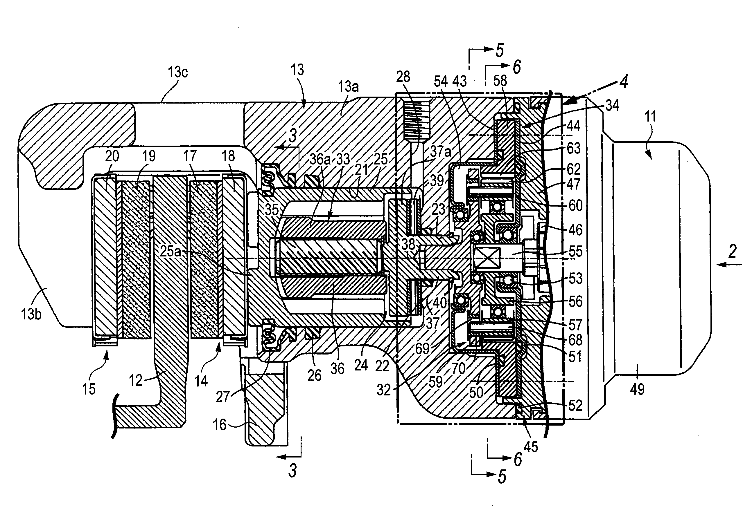
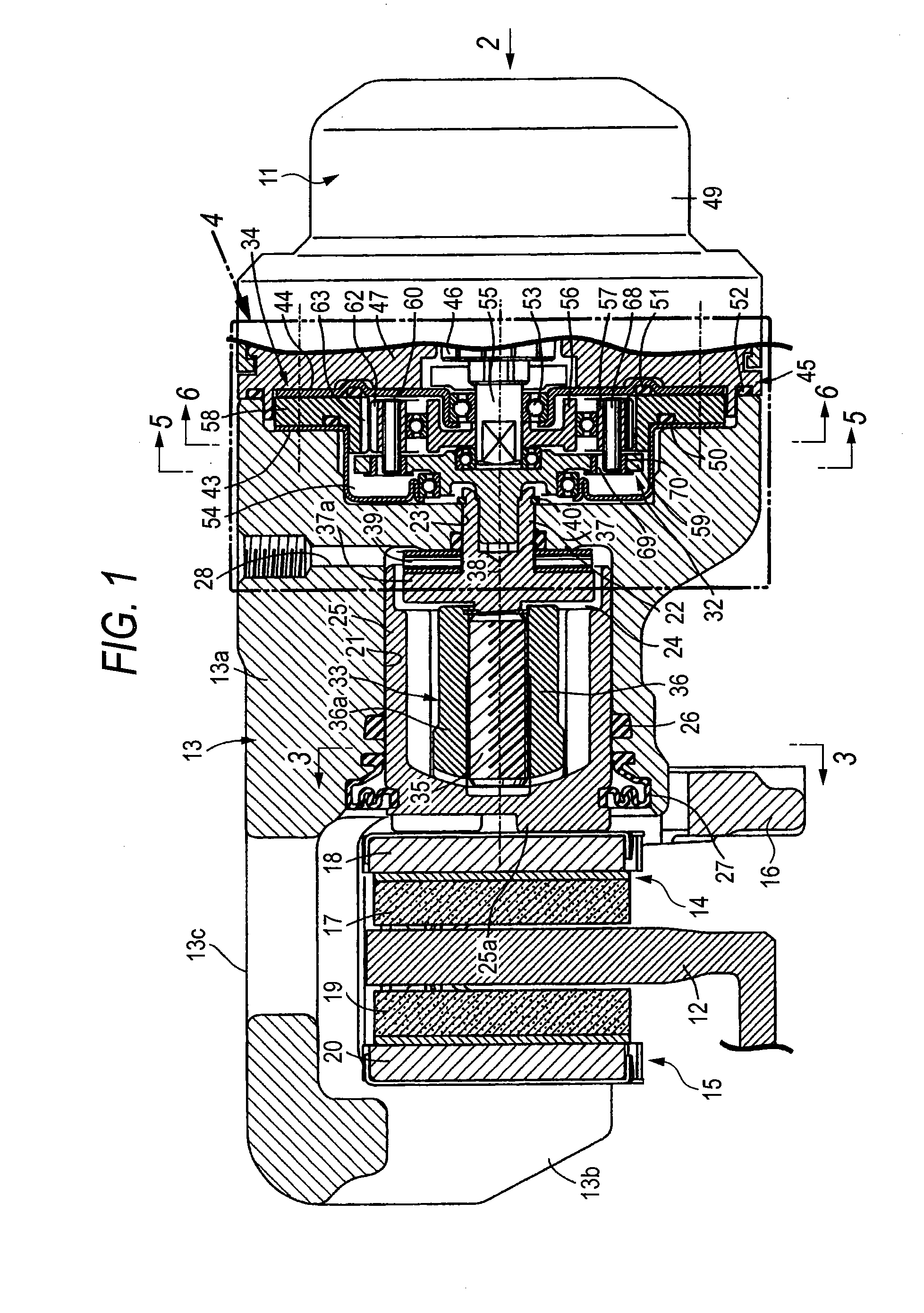
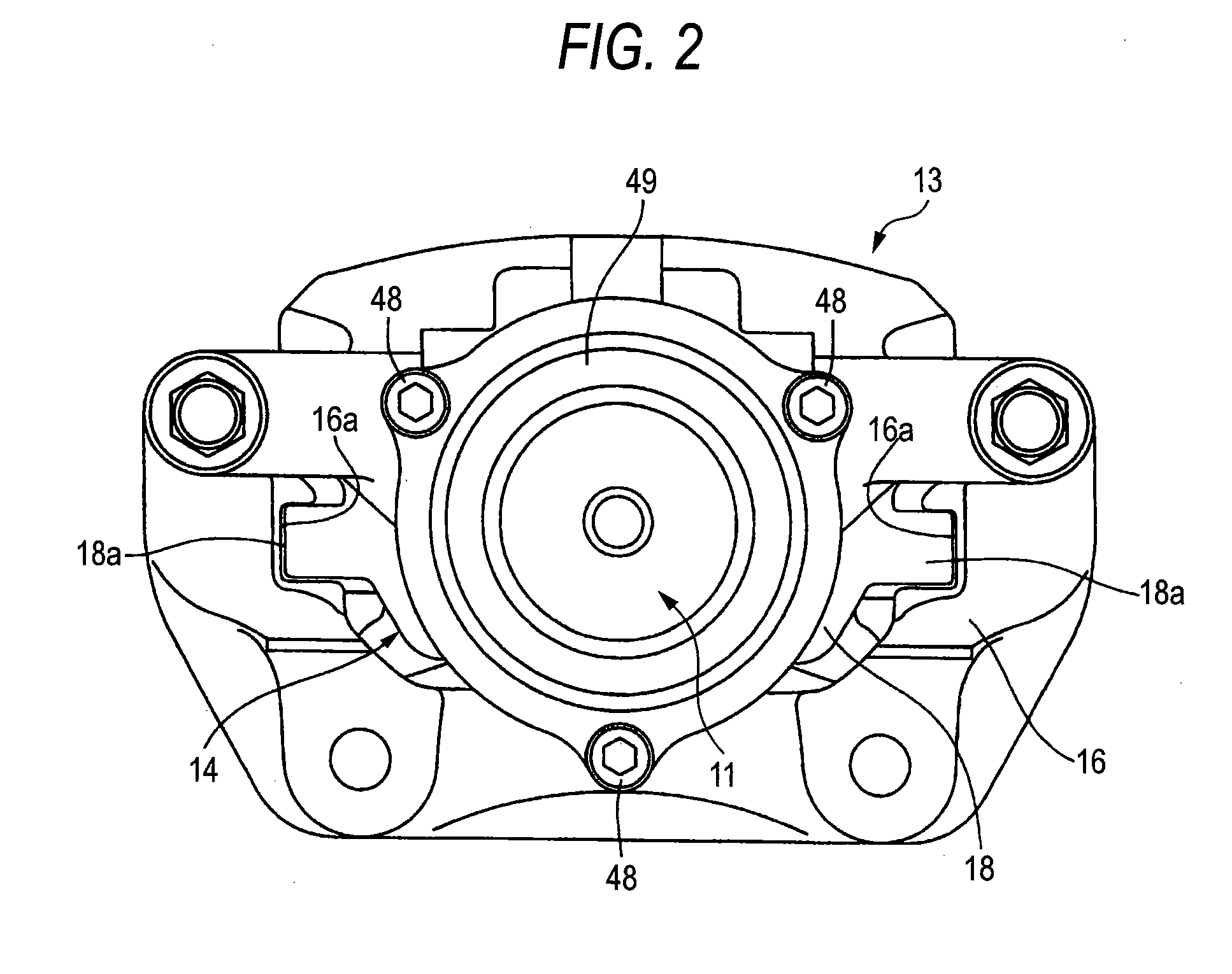
[0030]FIGS. 1 to 6 show an embodiment of the invention, where FIG. 1 is a longitudinal section view of a vehicular disc brake, FIG. 2 is a diagram as viewed in a direction of arrow 2 of FIG. 1, FIG. 3 is a cross-sectional view taken along line 3-3 of FIG. 1, FIG. 4 is an enlarged view of a part viewed in a direction of arrow 4 of FIG. 1, FIG. 5 is a cross-sectional view taken along line 5-5 of FIG. 1, and FIG. 6 is a cross-sectional view taken along line 6-6 of FIG. 1.

[0031]First, in FIGS. 1 and 2, the vehicular disc brake makes it possible to obtain a service brake state by a hydraulic pressure and also to obtain a service brake state and a parking brake state by operation of an electric motor 11. The vehicular disc brake includes a disc rotor 12 rotating together with a vehicle wheel (not shown), a caliper body 13 and a pair of friction pads 14 and 15 which are disposed ...


PUM


Abstract

A speed reducer 32 has an eccentric rotating member 56 which rotates along with a motor shaft 55 of an electric motor 11, an outer gear 57 which is rotatably supported by the outer circumference of the eccentric rotating member 56, an inner gear 58 which is fixedly disposed so as to be coaxial with the motor shaft 55 so as to engage with the outer gear 57, an output member 59 which is connected to an input member 37 of the motion converting mechanism 22 disposed so as to be coaxial with the motor shaft 55 so as to be not relatively rotatable about the input member 37, and an Oldham mechanism 60 which is disposed between the outer gear 57 and the output member 59 so as to transmit only a rotational component of the outer gear 57.

Description

BACKGROUND OF THE INVENTION[0001]1. Field of the Invention[0002]The present invention relates to a vehicular disc brake having a caliper body that supports a brake piston so as to be axially slidably and has an electric motor, a speed reducer that reduces output from the electric motor, a motion converting mechanism that converts a rotation output from the speed reducer into axial operation force of the brake piston and is interposed between the brake piston and the speed reducer. 2. Description of Related Art[0003]It is know in Japanese Patent Unexamined Publication JP-A-2001-263395 that vehicular disc brake having a motion converting mechanism that is disposed between a speed reducer for reducing power output from a motor shaft of an electric motor and a brake piston, and has axis line eccentric with the motor shaft In the vehicular disc brake, the speed reducer includes a pair of inner gears disposed in a pair of rotating members of the motion converting mechanism or the motor sh...

Claims


Application Information

Patent Timeline
Patent Type & Authority Applications(United States)
IPC IPC(8): F16D55/08F16D65/18
CPCF16D65/18F16H1/32F16D2125/50F16D2121/24
Inventor ADACHI, OSAMU
Owner NISSIN KOGYO CO LTD
Why Eureka
Try Eureka