Insulated pipe joint

a technology of insulated pipes and joints, applied in the direction of hose connections, manufacturing tools, mechanical equipment, etc., can solve the problems of forming wax or hydrates in the pipeline, damage to the surface of the pipe, and the coating applied to the surface that must be gripped by tools such as jaws, etc., to achieve convenient handling, low cost, and reliable coating

Active Publication Date: 2007-09-13
SINGLE BUOY MOORINGS INC
View PDF17 Cites 11 Cited by
  • Summary
  • Abstract
  • Description
  • Claims
  • Application Information

AI Technical Summary

Benefits of technology

[0005]In accordance with one embodiment of the invention, a method is provided for the preparation and installation of steel pipe sections into a long pipe string in a sea, which provides bare steel gripping surfaces on the ends of the pipe sections to facilitate handling them during their tandem connections, and while providing reliable coatings at minimal cost. Each pipe section is coated with an initial coating while the pipe section is located on land, with the initial coating extending along most of the pipe section length, except at the pipe ends. This leaves bare gripping surfaces at the pipe ends, that can be gripped by pipe handling equipment such as make-up tongs.

Problems solved by technology

Another is mechanical upsetting in which one pipe end is forcefully expanded to receive the other.
The coating is usually necessary also, to prevent excess cooling of hydrocarbons in the pipeline, which could result in the forming of wax or hydrates in the pipeline that could block it.
However, coatings applied to surfaces that must be gripped by tools such as jaws, will often be damaged by the tools.
Also, the tools often will not achieve a good grip on the relatively soft surfaces of coatings as compared to the steel surface of the pipe itself.

Method used


Image

  • Insulated pipe joint
  • Insulated pipe joint
  • Insulated pipe joint

Examples


Embodiment Construction

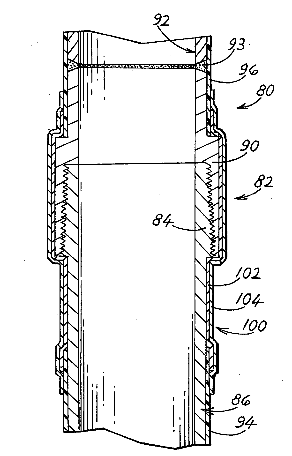
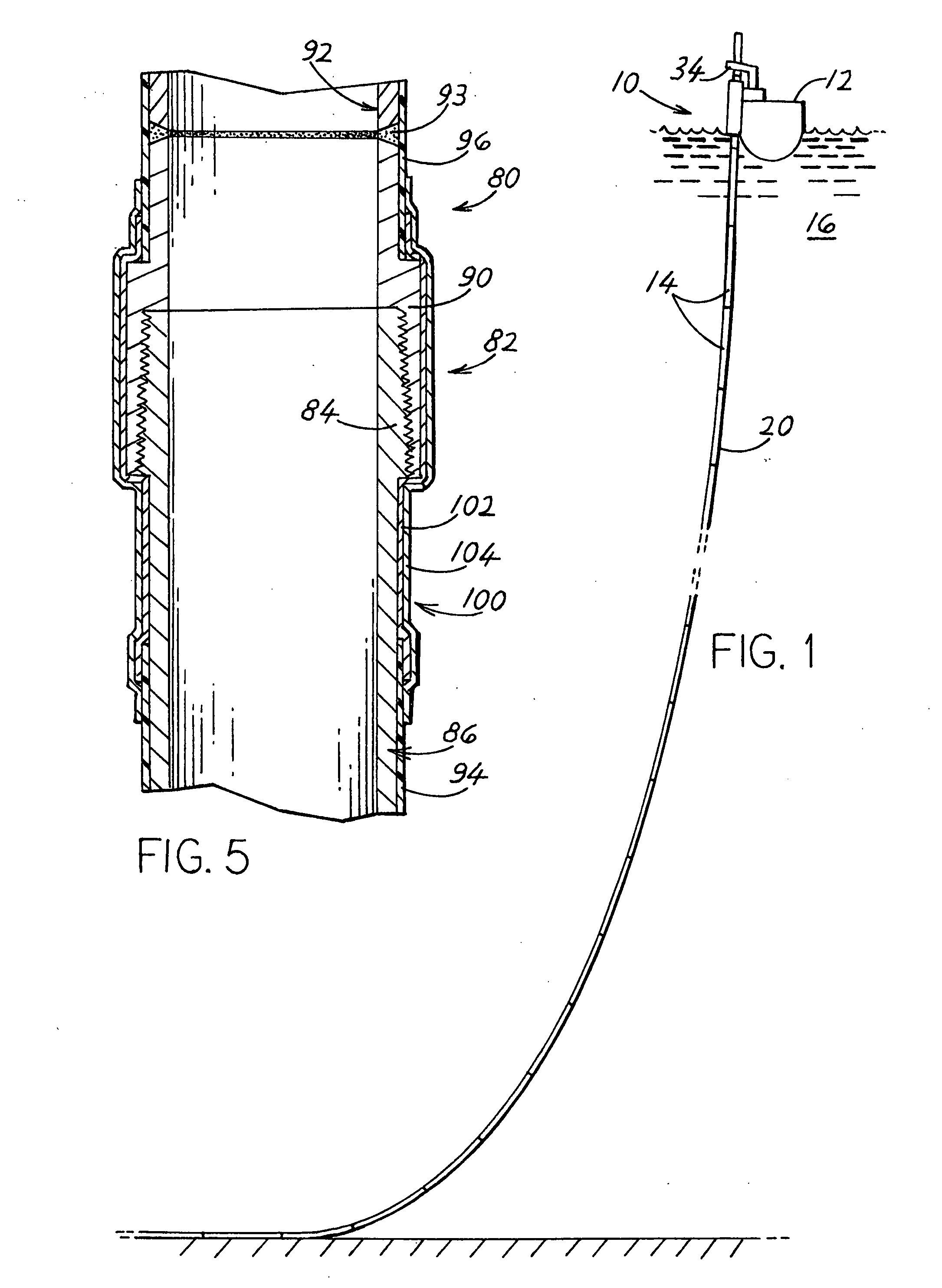
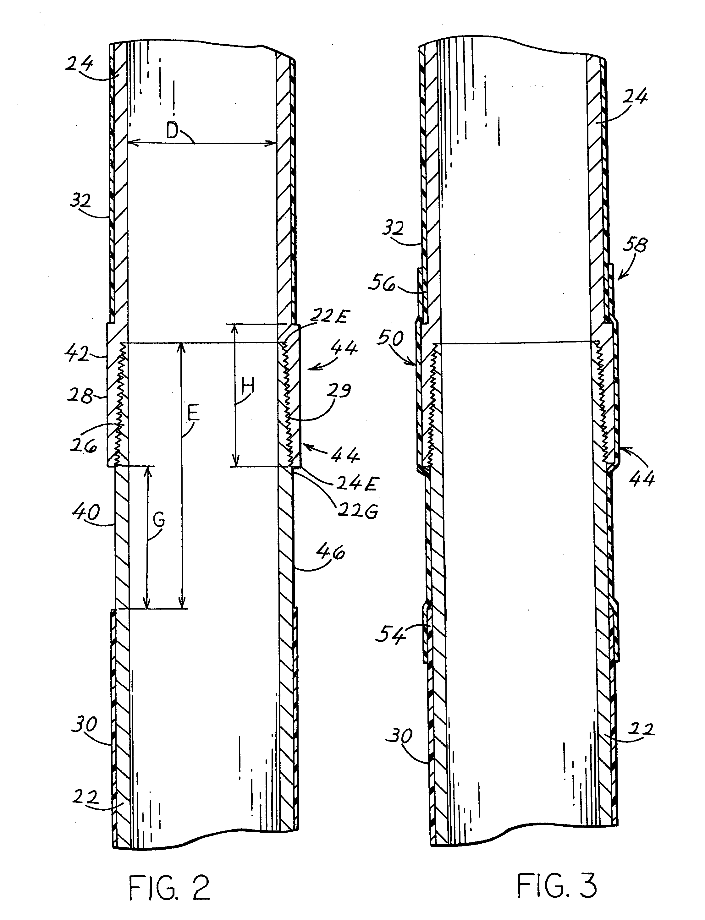
[0014]FIG. 1 shows an installation system 10 which includes an installation structure in the form of a platform or vessel 12 that is in the process of connecting pipe sections 14 in tandem and lowering them into the sea 16. The pipeline 20 formed by the tandem-connected pipe sections is to be used to carry hydrocarbons, as to carry hydrocarbons from an undersea well to a production vessel that will replace the installation vessel, or from a tanker to a receiving terminal, or in other applications. The pipe sections are formed of steel pipe and have coverings, or coatings that are combined with cathode protection to avoid corrosion in sea water. In many cases, the coating is also useful as a thermal insulator to prevent cooling of hydrocarbons passing though the pipeline, so as to avoid the formation of wax and hydrates that could block the pipeline.

[0015]The pipeline usually includes much more than ten pipe sections connected in tandem. Each pipe section typically has a length of 40...


PUM

PropertyMeasurementUnit
thicknessaaaaaaaaaa
thicknessaaaaaaaaaa
diameteraaaaaaaaaa

Abstract

A pipeline (20) that lies primarily in the sea and that consists of multiple steel pipe sections connected in tandem at pipe joints, includes a protective coating around the pipe sections and around the pipe joints. Each pipe section is first covered, at an onshore facility, by an initial coating (30, 32) that extends along at least 80% of the pipe section length while leaving its ends uncovered, to leave gripping areas (40, 42) where the steel of the pipe is uncovered so the pipe can be clamped by tools such as those with steel jaws to position and slide it axially, or turn it, or prevent it from turning. After a pair of pipe sections are connected, a completion coating (50) is applied around the pipe joint to leave the pipeline with a coating around all of it.

Description

CROSS-REFERENCE[0001]Applicant claims priority from U.S. provisional patent application 60 / 780,189 filed Mar. 8, 2006.BACKGROUND OF THE INVENTION[0002]Steel pipelines are widely used to carry hydrocarbons though the sea. Such a pipeline includes multiple steel pipe sections, each of a length such as 40 feet (12.2 meters) for pipe sections having a ten inch (0.254 m) diameter, with adjacent ends that are connected together. Many different techniques are used to connect adjacent ends together. One method is thermal expansion-shrinking where one pipe end is expanded with heat and the other one is shrunk with cold before interfitting them. Another is a braze coupling where brazing material (but not the pipe ends) is melted to join two pipe ends. Another is mechanical upsetting in which one pipe end is forcefully expanded to receive the other. Another is a castellated or ordinary thread coupling where a separate coupling with female threads threadably joins two male-threaded pipe ends. A...

Claims


Application Information

Patent Timeline
Patent Type & Authority Applications(United States)
IPC IPC(8): F16L25/00
CPCF16L1/206F16L58/182F16L59/18Y10T29/49982Y10T29/49865Y10T29/49885Y10T29/49888
Inventor POLLACK, JACKRIGGS, DAVID C.
Owner SINGLE BUOY MOORINGS INC
Why Eureka
Try Eureka