Insulation detecting method and insulation detecting device

Inactive Publication Date: 2007-09-13
YAZAKI CORP
View PDF10 Cites 45 Cited by
  • Summary
  • Abstract
  • Description
  • Claims
  • Application Information

AI Technical Summary

Benefits of technology

[0090]These and other objects, features, and advantages of the present invention will become more

Problems solved by technology

However, in the vehicle having the high voltage source, the high voltage changes owing to the running condition.
Thus, because the insulation is not detected accurately while the high voltage changes, the insulation is detected only w

Method used


Image

  • Insulation detecting method and insulation detecting device
  • Insulation detecting method and insulation detecting device
  • Insulation detecting method and insulation detecting device

Examples


first embodiment

[0103]A first embodiment of an insulation detecting method and an insulation detecting device will be explained with reference to figures.

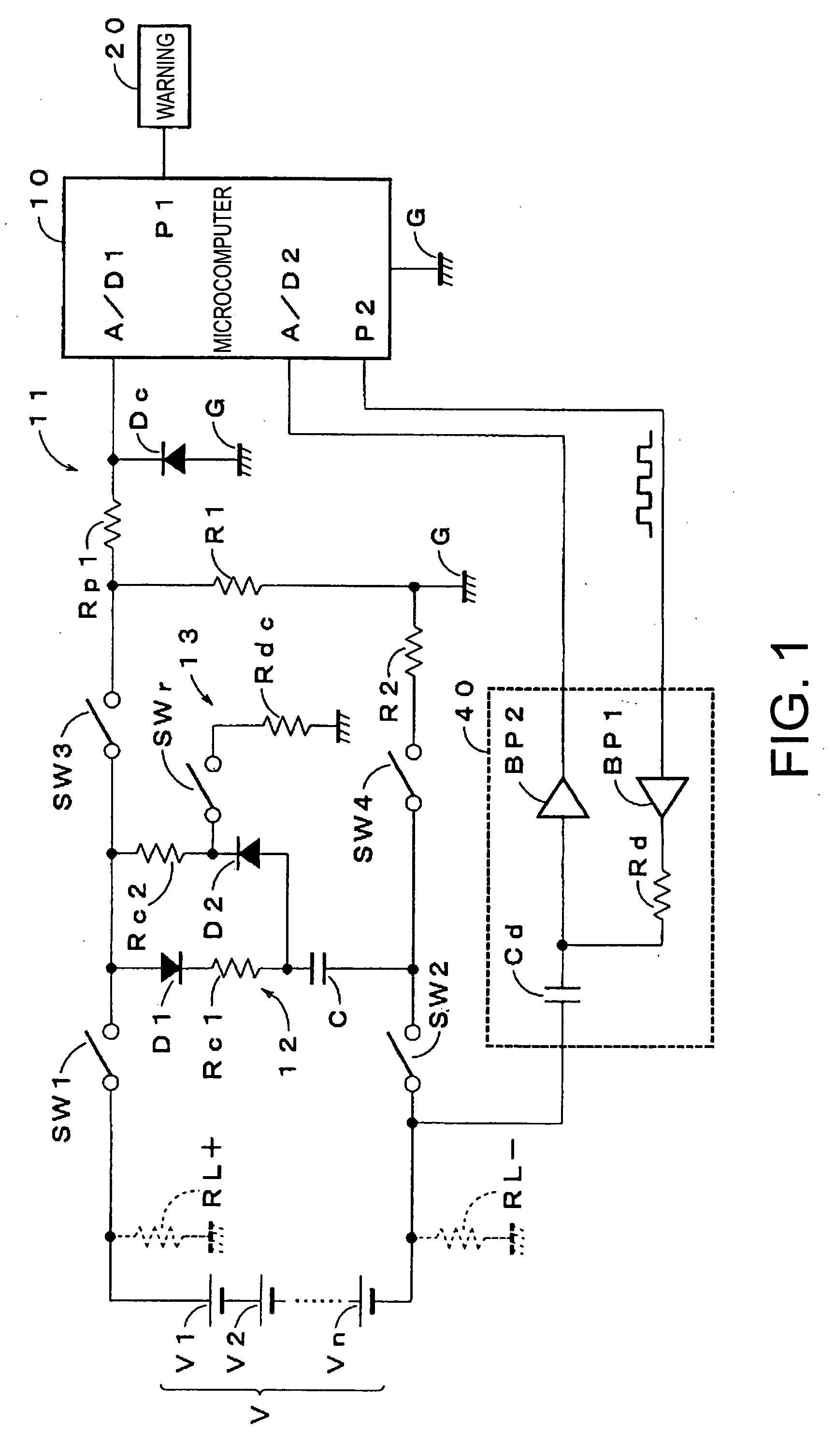
[0104]FIG. 1 is a circuit diagram showing a first embodiment of an insulation detecting device carrying out an insulation detecting method according to the present invention. A high voltage source (=direct current source) V composed of the number N of the batteries in series is isolated from a ground G of a low voltage system such as a microcomputer 10. The microcomputer 10 works as a voltage measuring member, a controlling member, an alternating signal generating member, a detecting member, a correction member, a resistance calculating member, a first average value measuring member, a second average value measuring member, a third average value measuring member, and a correction value calculating member in claims.

[0105]As shown in FIG. 1, the insulation detecting device includes a structure of a flying capacitor system, and includes a bipolar cap...

second embodiment

[0131]An insulation detecting device and an insulation detecting method according to the second embodiment of the present invention will be explained with figures.

[0132]FIG. 4 is a circuit diagram showing a second embodiment of an insulation detecting device carrying out an insulation detecting method according to the present invention. A high voltage source (=direct current source) V composed of the number N of the batteries in series is isolated from a ground G of a low voltage system such as a microcomputer 10. The microcomputer 10 works as a voltage measuring member, a first controlling member, a calculating member, and a controlling member in claims.

[0133]As shown in FIG. 4, the insulation detecting device includes a bipolar capacitor C, a first switch SW1 for connecting an anode of the high voltage source V to an end of the capacitor C, and a second switch SW2 for connecting a cathode of the high voltage source V to the opposite end of the capacitor C.

[0134]The microcomputer 1...


PUM


Abstract

An alternating signal from a signal generator is applied to a direct current source via a detecting resistor and a coupling capacitor. A detecting member detects a voltage amplitude change appeared at a contact between the detecting resistor and the coupling capacitor. Based on the voltage amplitude change, a correction member corrects a first measuring voltage when a capacitor is connected to a contact between an anode of the direct current source and a ground, and a second measuring voltage when the capacitor is connected to a contact between a cathode of the direct current source and the ground. Based on the corrected first and second measuring values and a voltage across the direct current source when the capacitor is connected to the anode and the cathode of the direct current source by a voltage measuring member, a calculation member calculates a resistance between the direct current source and the ground.

Description

CROSS REFERENCE TO RELATED APPLICATIONS[0001]This application is on the basis of Japanese Patent Applications No. 2006-062388, and No. 2006-065829 the contents of which are hereby incorporated by reference.BACKGROUND OF THE INVENTION[0002]1. Field of the Invention[0003]The present invention relates to an insulation detecting method and an insulation detecting device, in particular, for detecting a ground fault resistance of a direct current power source.[0004]2. Description of the Related Art[0005]As a conventional insulation detecting device, for example, a flying capacitor type insulation detecting device is proposed. This insulation detecting device detects an insulating state of a direct current high voltage power source by calculating a ground fault resistance based on a measured voltage of a high voltage charged capacitor floating from the ground (namely, a flying capacitor), and a measured voltage of a high voltage charged capacitor of which one electrode is connected to the ...

Claims


Application Information

Patent Timeline
IPC IPC(8): G01R31/02
CPCG01R31/44
Inventor KAWAMURA, YOSHIHIRO
Owner YAZAKI CORP
Why Eureka
Try Eureka