Mapping and Detection of Pipelines using Low Power Wireless Sensor Network

a wireless sensor and pipeline technology, applied in the direction of burglar alarm mechanical actuation, using reradiation, instruments, etc., can solve the problems of most costly and dangerous type of accident, death and destruction, unintentional damage to underground facilities during excavation, etc., to achieve low power wireless, small size, and low cost.

Inactive Publication Date: 2007-09-13
SABATA ASHOK +1
View PDF4 Cites 69 Cited by
  • Summary
  • Abstract
  • Description
  • Claims
  • Application Information

AI Technical Summary

Benefits of technology

[0011] The present invention is directed to a system and method for mapping of subsurface infrastructure such as gas pipelines, water main, utility conduit, and fiber optic conduit with a low power wireless sensor network that is small, low cost, and rugged. In certain embodiments the system includes ultrasonic sensors, radio frequency sensors, acoustic sensors, and potentially a plurality of other active and passive sensing devices with wireless transceivers that together determine the exact location of the sensor when the sensor is placed in close proximity of the infrastructure.
[0013] In at least one embodiment, the wireless network is configured using a Mesh Network consisting of a “mesh” of interconnected wireless transceivers. The network uses multi-hop routing that reduces power requirements.
[0016] The present invention is a substantial advancement over prior systems and methods of locating subsurface infrastructure. Because the present invention utilizes low cost wireless devices called motes, the present invention also has the advantage that it does not require the extensive use of wires to transmit communication signals.

Problems solved by technology

. . unintentional damage to underground facilities during excavation is a significant cause of disruptions in telecommunications, water supply, electric power, and other vital public services, such as hospital and air traffic control operations, and is a leading cause of natural gas and hazardous liquid pipeline accidents.” According to the DOE (Department of Energy), third-party damage, which occurs when construction or excavation crews inadvertently strike underground utility lines, is by far the most costly and dangerous type of accident.
Despite the successful implementation of One-Call systems in most of the U.S., a wide variety if impacts still occur resulting in accidents ranging from a clogged residential sewer line to a gas explosion causing death and destruction.
Overall, the direct and indirect costs of such accidents are staggering making the use of more sophisticated prevention approaches also economically prudent.
Each of these methods individually has limitations, so integrated systems combining the 2 techniques have therefore been developed.
Though the integrated combination has increased the accuracy of locating subsurface infrastructure, the cost and the size of the equipment make it difficult for every excavator to have one of these onsite.
Vibrations in the ground (created by construction equipment) cause compressions in the soil surrounding the pipeline and if the vibrations and soil compressions are sufficiently close to the pipeline, the fiber-optic cable will bend.
Even a minute deformation in the cable will change its light transmission and reflection properties and send an early warning of a potentially hazardous encroachment.
Though there is considerable ongoing research activity in identifying a commercially viable method for locating pipelines and other subsurface infrastructure to prevent third party damage all the proposed solutions are either expensive and / or highly complex for widespread implementation and often times give false alarms.
The sensor nodes are often inexpensive and have limited computation, memory, and communication capability and typically consume low power therefore are generally expected to be long-lived, untethered, and unattended for extended periods of time (years); the nodes typically communicate using short-range wireless communication.

Method used


Image

  • Mapping and Detection of Pipelines using Low Power Wireless Sensor Network
  • Mapping and Detection of Pipelines using Low Power Wireless Sensor Network
  • Mapping and Detection of Pipelines using Low Power Wireless Sensor Network

Examples


Embodiment Construction

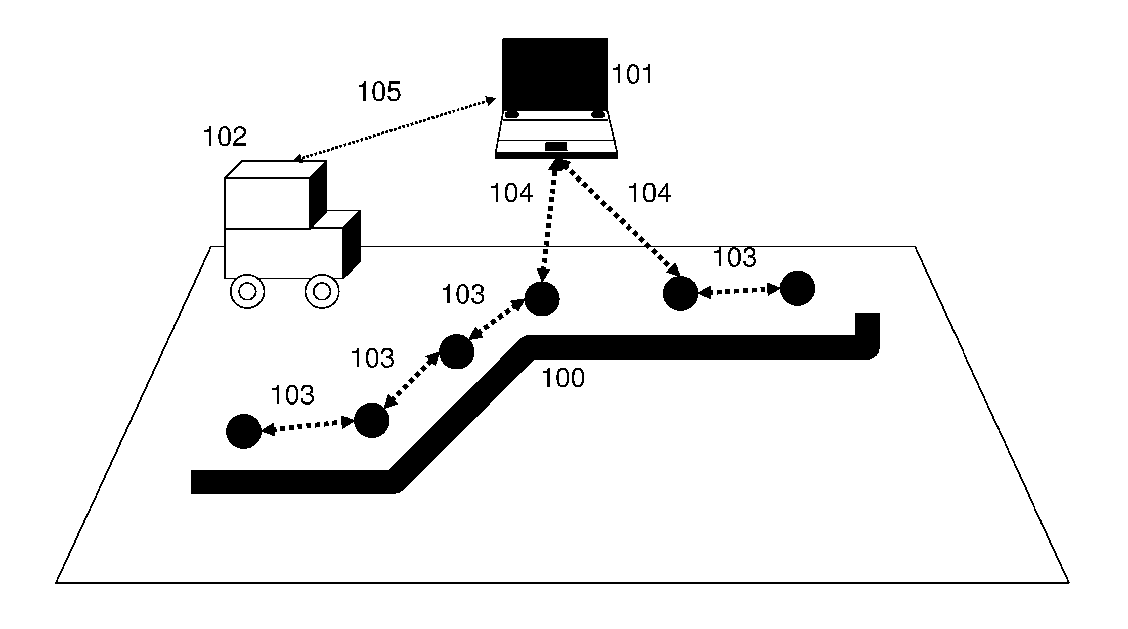
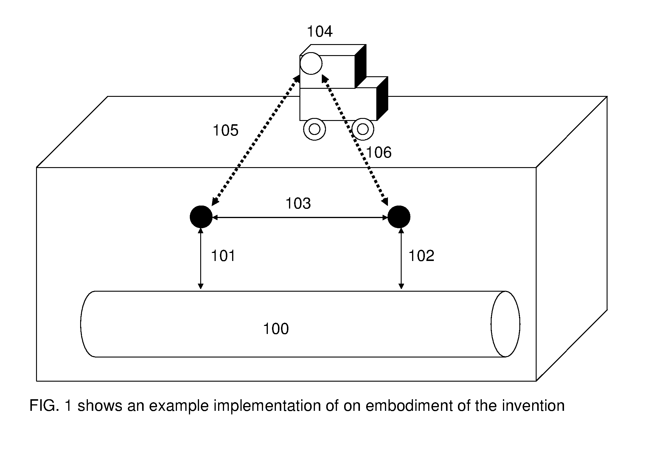
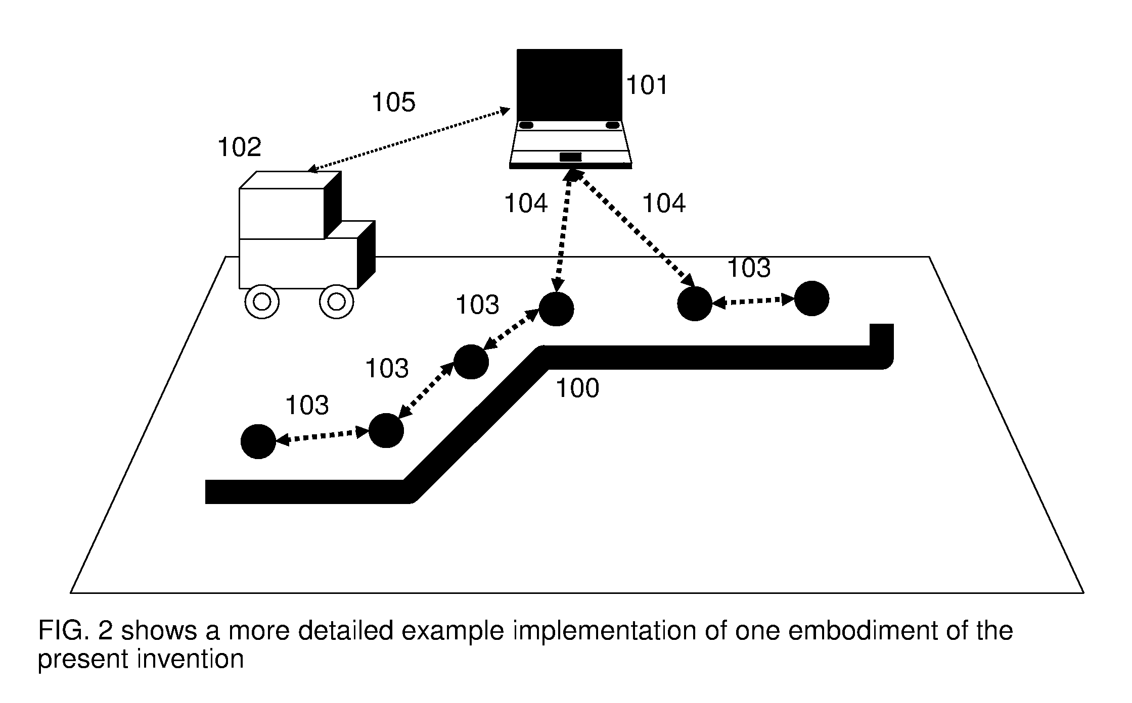
[0021] To more fully appreciate aspects of certain embodiments of the present invention, a brief discussion of techniques proposed in the prior art for collecting measurement data from wireless sensor networks is appropriate. Wireless sensor networks are usually implemented as a collection of small sensor devices (or “nodes”) communicating over low-power wireless links and powered by a battery. As mentioned above, the nodes of a wireless sensor network may be distributed in an ad-hoc manner. In such ad-hoc sensor networks, the communication between the sensor nodes is typically established via protocols that self-configure the ad-hoc network, as opposed to the designed communication topology of traditional networked measurement systems. Because these sensor nodes generally run on battery power and are expected to last for several years, severe constraints are typically placed on the amount of computation, and particularly on the amount and range of communication of the sensor nodes....


PUM


Abstract

A wireless sensor network will be used to detect the location of subsurface infrastructures such as a pipeline. The objective is to alert the infrastructure operator and the construction equipment operator of the threat of damage to the infrastructure. Currently the equipment operator has to depend on the color marks made by the locater sent by the One-Call center. The low cost wireless sensor network will alert the operator when the machine tool gets close to an existing utility. A combination of radio frequency signal, ultrasonic pulse, and acoustic signals is used to determine the infrastructure location. A sensor network is then used to map the infrastructure location with respect to the construction equipment operator and provide a reliable, accurate system to alert the operator of the potential danger.

Description

TECHNICAL FIELD [0001] The current invention relates to the detection and mapping of subsurface infrastructures such as pipelines using a network of wireless sensors. In particular it relates to methods and systems that use a network of wireless mobile sensors to detect and warn in real time the existence of subsurface infrastructure. BACKGROUND OF INVENTION [0002] The congressional Transportation Equity Act for the 21st Century, TEA 21, Title VII, Subtitle C, SEC. 87301, states that: “. . . unintentional damage to underground facilities during excavation is a significant cause of disruptions in telecommunications, water supply, electric power, and other vital public services, such as hospital and air traffic control operations, and is a leading cause of natural gas and hazardous liquid pipeline accidents.” According to the DOE (Department of Energy), third-party damage, which occurs when construction or excavation crews inadvertently strike underground utility lines, is by far the ...

Claims


Application Information

Patent Timeline
Patent Type & Authority Applications(United States)
IPC IPC(8): G08B21/00G08B13/14G01V3/08
CPCG01V2210/6163G01V11/00
Inventor SABATA, ASHOKSABATA, BIKASH
Owner SABATA ASHOK
Why Eureka
Try Eureka