Diffraction type light-condensing film and planar light source device using the same

a light-condensing film and film-type technology, applied in the direction of diffraction gratings, optics, instruments, etc., can solve the problems of affecting the uniformity of brightness, hindering the miniaturization of lcds, and affecting the quality of images, so as to achieve high brightness and high brightness uniformity. uniformity, high light transmittance and light-condensing ability

Inactive Publication Date: 2007-09-13
HITACHI CHEM CO LTD
View PDF1 Cites 20 Cited by
  • Summary
  • Abstract
  • Description
  • Claims
  • Application Information

AI Technical Summary

Benefits of technology

[0010] There is provided a diffraction type light-condensing film that is thin, has a high light transmittance and light-condensing ability, and is easy to handle, as well as a planar light source device using the same.

Problems solved by technology

In the vicinity of the light-entering part of a side-incidence backlight, the uniformity of the brightness is so inferior as to deteriorate the quality of the image displayed on the LCD panel placed over the backlight.
Due to the low uniformity, the region within a certain distance from the light-entering part must be reserved as an undisplayed area, which hinders the miniaturization of LCD's.
It is difficult for conventional prism sheets to simultaneously realize high brightness and high brightness uniformity.
The dispersion deteriorates the color reproduction of liquid crystals to degrade display quality.
With the macroscopic geometry, geometric-optical sheets, including the prism sheet, cannot help remaining thick.
Thus, the prism sheet is an obstacle in the attempt to make thinner backlight.
As each prism in the prism sheet independently functions to bend light, and defect or foreign matter in the prism results in an anomalous scattering of the light that passes through the prism.
A display is sensitive to the defect or foreign matter and causes a display abnormity, to deteriorate product quality.
Such a hologram optical element using the diffraction / interference phenomenon based on wave optics has problems of 1) producing diffracted light of orders of diffraction other than that at which incident light is vertically diffracted, 2) lowering the diffraction efficiency of the required order of diffraction, and 3) causing large wavelength dispersion.
If a depth is improper, the diffraction efficiency of the required order of diffraction will be low.

Method used


Image

  • Diffraction type light-condensing film and planar light source device using the same
  • Diffraction type light-condensing film and planar light source device using the same
  • Diffraction type light-condensing film and planar light source device using the same

Examples


embodiment

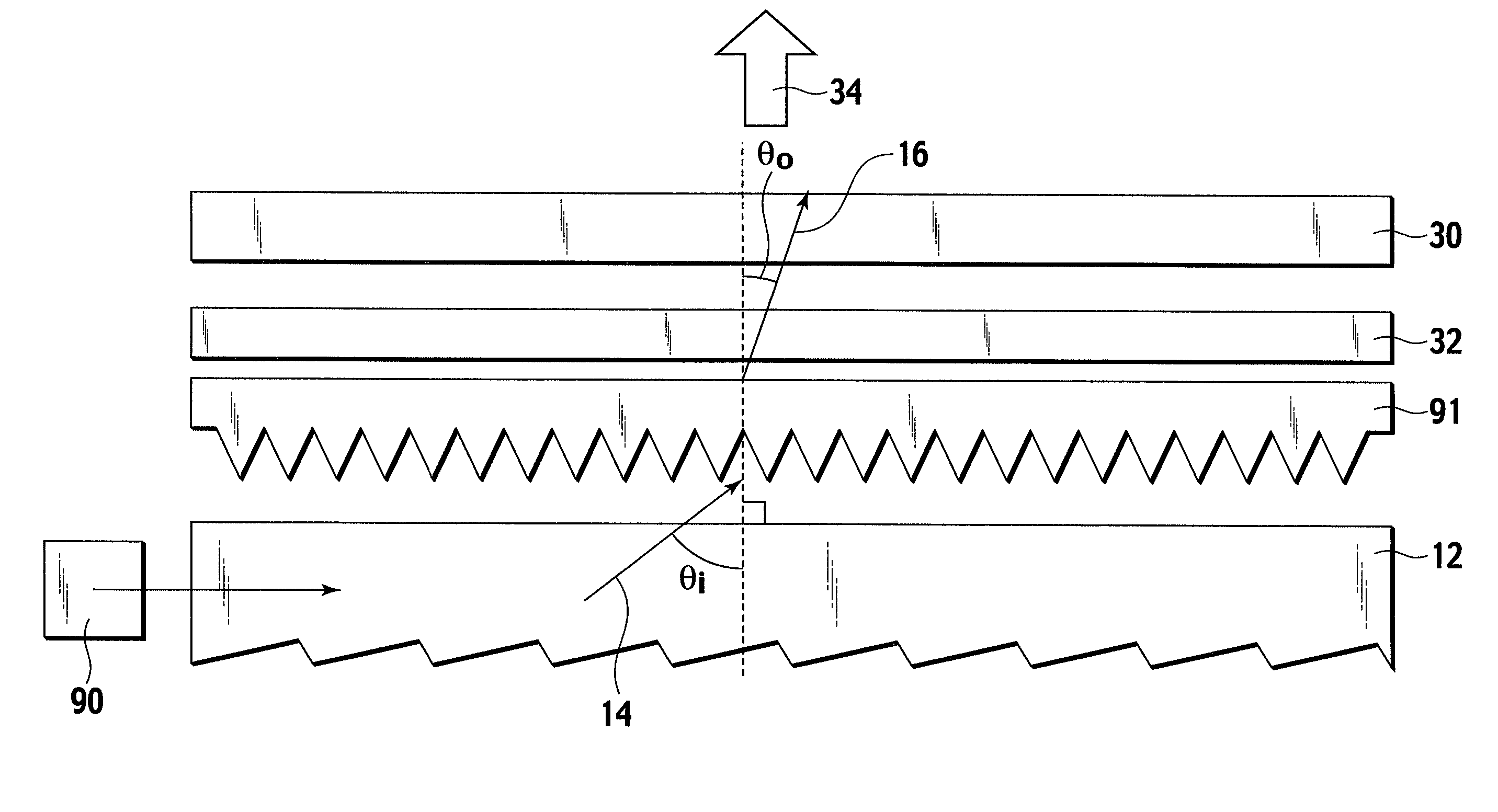
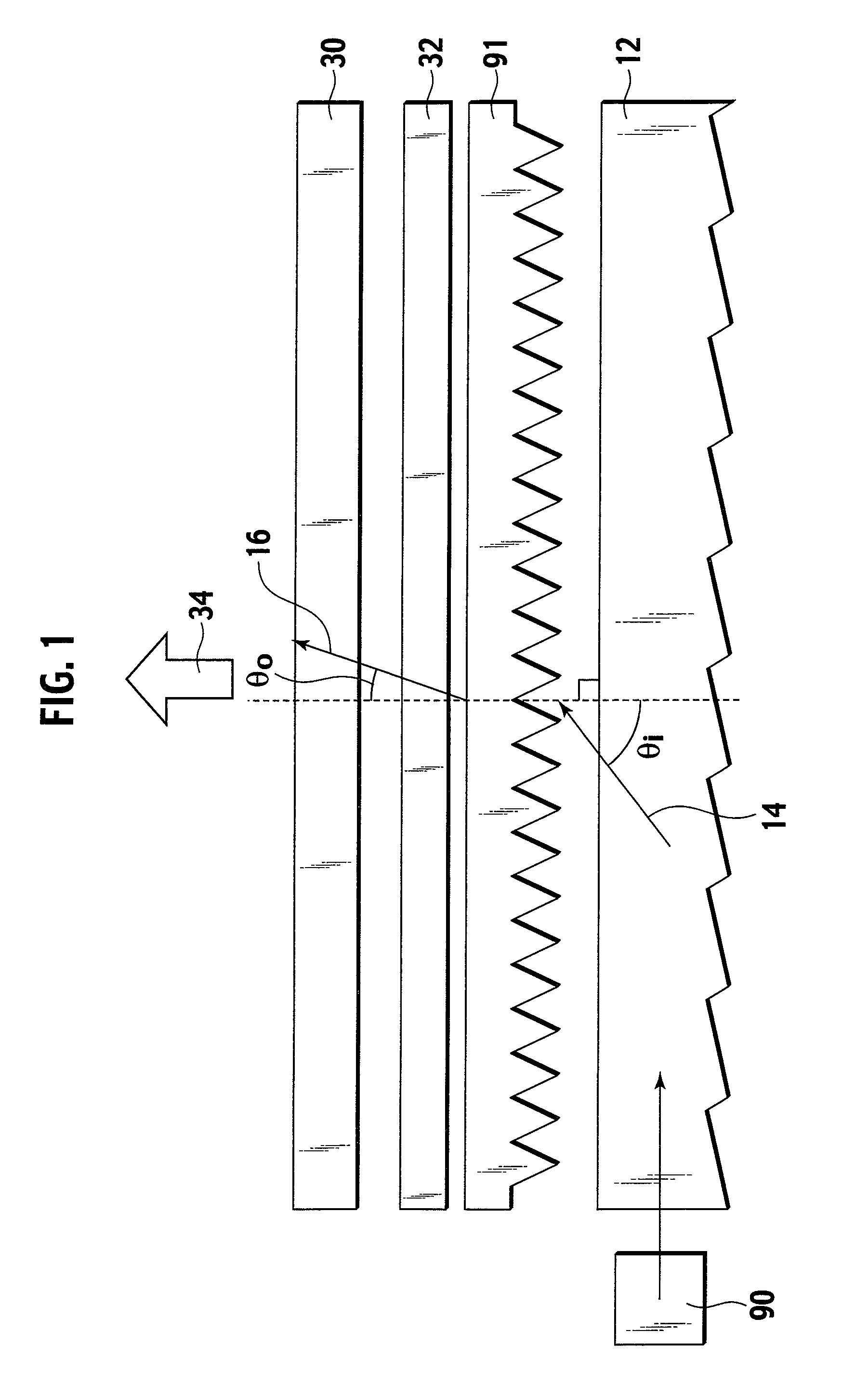
[0111]FIG. 13 shows a backlight structure employing a light guide 48 according to an embodiment. This backlight structure is for a small liquid crystal display such as of a cellular phone. From a lower side of the drawing, the backlight consists of a reflection plate 56, the light guide 48, a hologram diffuser 46, and a diffraction type light-condensing film (light bending diffraction grating) 10. The light guide 48 and hologram diffuser 46 are integrally formed. Along a light incident end face 52 of the light guide 48, there is a LED light source 54. In this structure, light emitted from the LED light source 54 is made incident to the light incident end face 52 of the light guide 48. The incident light is totally reflected several times by reflection grooves formed on a back surface 50 of the light guide and is output from the hologram diffuser 46 formed on an output surface of the light guide. The diffraction type light-condensing film 10 diffracts the light in a vertical directio...


PUM


Abstract

Provided are an easy-to-handle thin diffraction type light-condensing film exhibiting high light transmissivity and condensation ability, and a planar light source device using the film. A hologram optical element using diffraction/interference phenomena based on wave properties of light is used instead of a conventional prism sheet using refraction. As a result, the diffraction type light-condensing film and the planar light source device have high light transmissivity and are thin. In the diffraction type light-condensing film, dependence of bending angle on wave length is low and light entering from an oblique direction is bent in the vertical direction and emitted with spectral separation of white light suppressed. High light-condensation impossible in a conventional optical element is realized by suppressing angular variation in emission light for angular variation in incident light.

Description

TECHNICAL FIELD [0001] The present invention relates to a diffraction type light-condensing film for bending oblique incident white light to a vertical direction and outputting the bent light and a planar light source device using the same. In particular, the present invention is applicable to a backlight of a liquid crystal display, to improve the brightness of the display in the direction of an observer. BACKGROUND TECHNOLOGY [0002] Liquid crystal displays (LCDs) are used as display parts of computers, display parts of control panels of home appliances, and display parts of cellular phones and are required to further reduce power consumption, weight, and thickness. [0003] The liquid crystal display is not a self-luminous device, and therefore, must have an external light source or environmental external light. The typical external light source is a backlight, which is a planar light source placed behind an LCD panel. The backlight is required to emit the outgoing light in the dire...

Claims


Application Information

Patent Timeline
Patent Type & Authority Applications(United States)
IPC IPC(8): G02B5/18
CPCG02B5/1871G02F1/133615G02B6/005G02B5/18G02B6/0001G02F1/1335G02B5/32
Inventor KOMATSU, TOKUTAROAWANO, YASUHIKO
Owner HITACHI CHEM CO LTD
Why Eureka
Try Eureka