Application of hardware-based mailboxes in network transceivers and distributed approach for predictable software-based protection switching

a software-based protection and mailbox technology, applied in data switching networks, multiplex communication, digital transmission, etc., can solve the problems of shared redundant routing that may suffer from longer switchover times, cost of consuming bandwidth, loss of potentially valuable data, etc., to achieve fast and reliable performance, reduce latency, and save host processor resources

Active Publication Date: 2007-09-13
INFINERA CORP
View PDF29 Cites 24 Cited by
  • Summary
  • Abstract
  • Description
  • Claims
  • Application Information

AI Technical Summary

Benefits of technology

[0011] According to this invention, automatic protection switching (APS) is quickly and reliably performed on redundant signal paths processed by a plurality of line cards, so-called digital line modules (DLMs), in a network node. Each line card contains a local memory coupled to a local controller and a local logic circuit. The local memory in the line card, also referred to as a mailbox (mbox), stores state information for signals processed by the line card itself, as well as state information for signals processed by other line cards, e.g., cards that process a working or protection path of the same signal. By storing the state of all the signals processed by all the line cards, the individual line card can locally and autonomously decide the control state of the signals processed on its line card, using local logic circuits and interrupts to its own local controller, all without interrupting a central controller, e.

Problems solved by technology

However shared redundant routing may suffer from longer switchover times because of latency in the transmission of control information.
Dedicated redundant routing overcomes these limitations by constantly communicating the signal on both the working and protection path, albeit at the cost of consuming bandwidth.
Every millisecond of interruption means the loss of potentially valu

Method used


Image

  • Application of hardware-based mailboxes in network transceivers and distributed approach for predictable software-based protection switching
  • Application of hardware-based mailboxes in network transceivers and distributed approach for predictable software-based protection switching
  • Application of hardware-based mailboxes in network transceivers and distributed approach for predictable software-based protection switching

Examples


Embodiment Construction

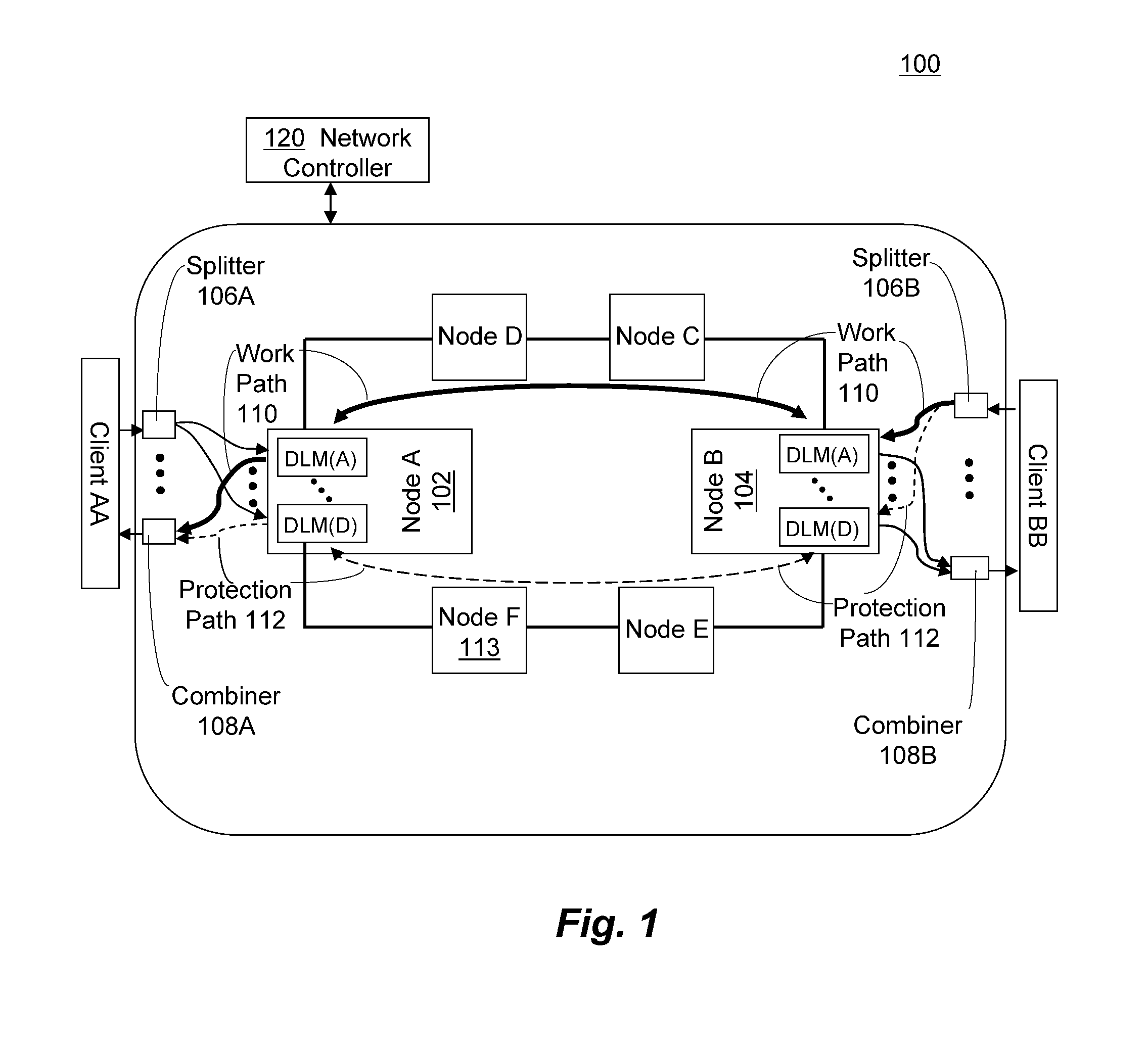
[0022] Reference is first made to FIG. 1 that illustrates a communication network 100 utilizing protection paths, in which this invention may be employed. In FIG. 1, a signal to be transmitted between client AA at node A 102 to client BB at node B 104, via both a working path 110 through nodes C and D, and a redundant protection path 112 though nodes E and F.

[0023] Redundant paths are created at both nodes A 102 and B 104 by the use of a splitter 106A and 106B, respectively. Thus a given client signal is replicated and sent into the line card of the node for transmission over the working path and the protection path. Similarly a given client signal transmitted over multiple paths, e.g., the working path and protection path, is combined at a junction, e.g., via combiners 108A and 108B at nodes A and B respectively, either for egressing the network to a client, or for progressing from one node to the next within the same network. The node controls which of the received redundant path...


PUM


Abstract

A line card in a network node having a local memory coupled to a local controller and local logic circuit. The local memory in the line card stores state information for signals processed by the line card itself, as well as state information for signals processed by other line cards. The logic circuit and controller implement a same fault detection and signal processing algorithms as all other line cards in the group, to essentially effectuate a distributed and local hardware based control of automatic protection switching (APS) without interrupting a central processor. The line card also performs error checking and supervisory functions to ensure consistency of state among the line cards.

Description

CROSS REFERENCE TO RELATED PATENT APPLICATIONS [0001] This application claims priority to U.S. Provisional Application Ser. No. 60 / 763,251, entitled “Application of hardware-based mailboxes in network transceivers and Distributed approach for Predictable Software-Based Protection Switching,” filed Jan. 30, 2006, which application is incorporated herein by reference in its entirety.BACKGROUND OF THE INVENTION [0002] 1. Field of the Invention [0003] This invention relates generally to network protection systems and more particularly to protection schemes for such systems to provide protection switching for optical signals in an optical transport network [0004] 2. Description of the Related Art [0005] For high-reliability signals, such as those used in telecommunications and data communications, duplicate versions of the signal are routed through the network, e.g., optical such as a synchronous optical network (SONET), via different paths, referred to as a working path and a protection...

Claims


Application Information

Patent Timeline
IPC IPC(8): H04L12/56
CPCH04J14/0283H04J14/0287H04J14/0295H04L45/22H04Q2011/0092H04L45/62H04Q11/0062H04Q2011/0016H04Q2011/0081H04L45/28H04L45/247
Inventor TRISNO, TJANDRASPRAGUE, EDWARD E.YOUNG, SCOTT A.
Owner INFINERA CORP
Why Eureka
Try Eureka