
System and method for demand limiting resistive load management

Active Publication Date: 2007-09-13
INVENSYS SYST INC +1
View PDF16 Cites 93 Cited by
  • Summary
  • Abstract
  • Description
  • Claims
  • Application Information

AI Technical Summary

Benefits of technology

[0007]The present invention generally relates to a system and method for limiting the electricity consumption of a resistive load device located within a premise. The method and apparatus allows the electricity demand limiting system to control the demand for electricity at either a single resistive load device within the premise or the demand for electricity for the entire premise.
[0008]The demand limiting system includes a consumption control circuit that is positioned between the electricity delivery system and the resistive load device. Preferably, the consumption control circuit is a triac-based control circuit that is operable to regulate the electricity consumption of the resistive load device at an infinite number of levels. When the consumption control circuit receives a control signal indicating that electricity consumption should be limited, the triac-based control circuit clips portions of the input sine wave to reduce the amount of electricity available for consumption by the resistive load device.
[0012]In one embodiment, the load controller can monitor the amount of electricity consumed by the resistive load device and determine the thermodynamic gain characteristics of the resistive load device and historical run time and consumption data of the resistive load device. Based upon these historic values, the load controller can determine the required thermal recovery demand and ability of the resistive load device and control the operation of the resistive load device to meet the demand accordingly. An example would be an electric hot water heater that recognizes a demand for hot water at 6:30 AM daily and is able to satisfy that demand in 30 minutes. This could represent a demand for or usage of 35 gallons of hot water for a shower. If this demand pattern is consistent, the load control device can learn to manage the reheating of water at a much slower rate and at a greatly reduced demand level. This type of pattern recognition and management of high resistive loads can result in a significant reduction on the total demand for energy on the energy delivery system. The management of resistive or emergency heating strips in a central heating system can be managed in an similar fashion.

Problems solved by technology

Resistive loads typically are large heating elements that consume a large amount of energy when energized and typically operate under the control of a thermostatic controller.
Because the load is resistive and large, it represents a significant portion of the total demand placed on an energy delivery system by the customer premise.
By using demand metering, the utility can recover the costs associated with meeting the maximum demands of the consumer, while not penalizing those customers who keep their demand on the system at a more consistent level.

Method used


Image

  • System and method for demand limiting resistive load management
  • System and method for demand limiting resistive load management

Examples


Embodiment Construction

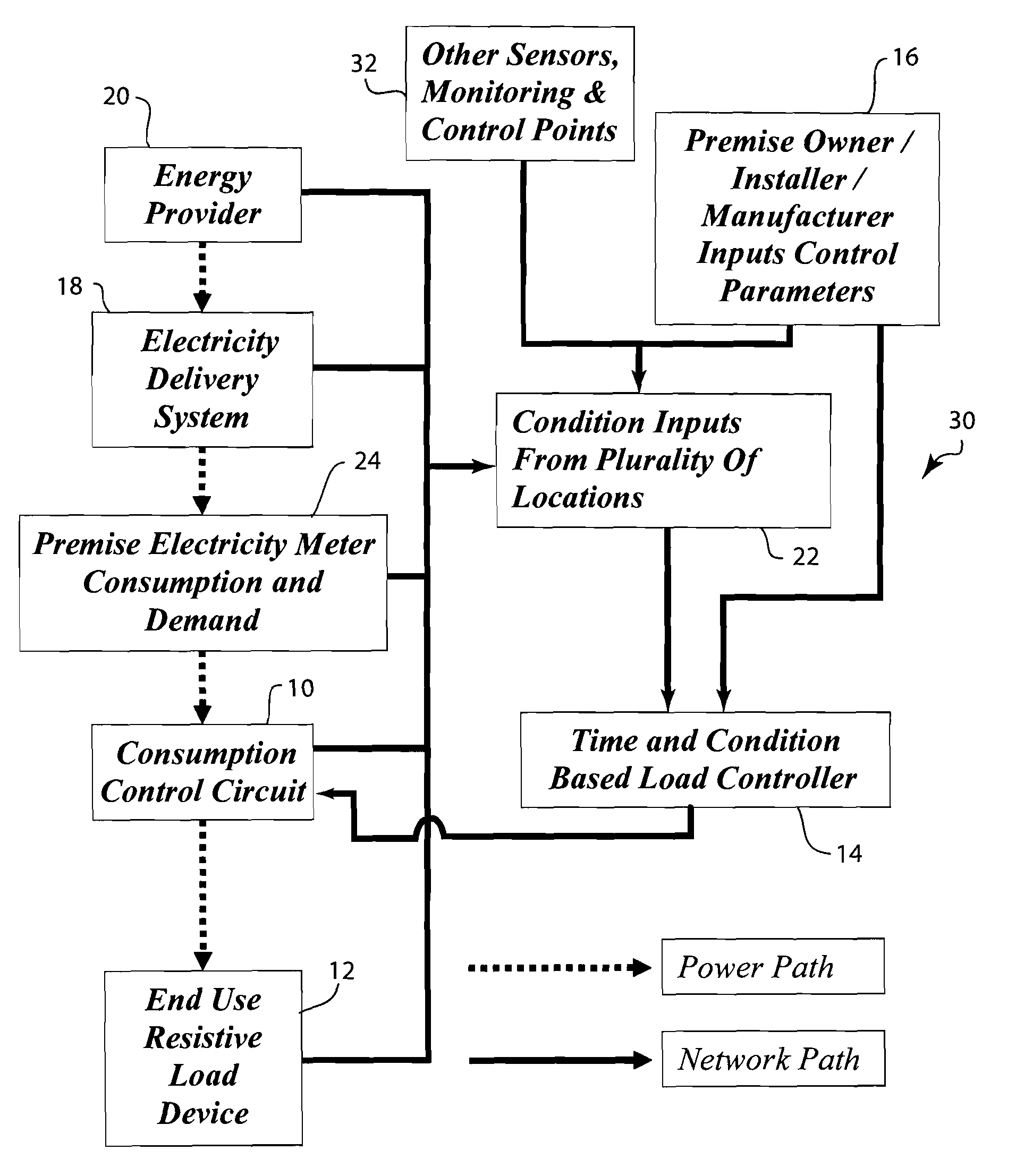
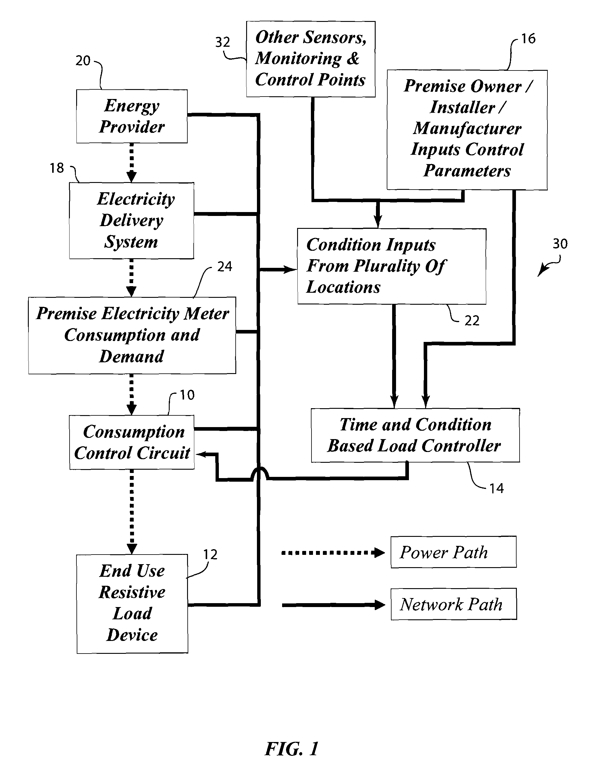
[0016]The invention combines a number of technologies into a system that will manage demand of resistive loads. The invention is designed to limit and / or manage the impact of resistive loads on the premise and the energy delivery system. This management is based on control parameters supplied to the system by anyone of a number of sources, including but not limited to, the premise owner, the installer of the system, an energy provider, the manufacturer of the appliance, the manufacturer of the control system and an energy services company.

[0017]The core of the resistive load demand limiting system shown in FIG. 1 is a triac-based control circuit 10 similar to the one described in U.S. Pat. No. 5,652,503, the disclosure of which is incorporated herein by reference. This triac control circuit 10 regulates the flow of power to a resistive load 12 by clipping the sine wave of the AC power using an embedded processor. If half the sine wave is clipped using this circuit, the total demand ...


PUM


Abstract

An electricity demand limiting system for limiting the electricity consumption of at least one resistive load device. The demand limiting system includes a consumption controller associated with the resistive load device that is operable to infinitely vary the amount of electricity being consumed by the load device. The consumption control device is in operative communication with a load controller such that the load controller can generate a control signal to affect the operation of the consumption control circuit. Preferably, the consumption control circuit is a triac-based circuit that receives the control signal from the load controller and limits the amount of electricity consumed by the resistive load device. The load controller can receive input signals from sensors monitoring the electricity delivery system or from the premise electricity meter. Further, the load controller can receive external inputs from a third party that determine the operation of the load controller in limiting the electricity demands of the resistive load device.

Description

CROSS REFERENCE TO RELATED APPLICATION[0001]The present application is based on and claims priority to U.S. Provisional Patent Application Ser. No. 60 / 780,591, filed on Mar. 9, 2006.BACKGROUND OF THE INVENTION[0002]The present invention relates to an electricity demand limiting system for resistive loads that is controlled using at least one of a schedule, a real time condition control signal, a user defined willingness to pay decision table, a device or premise demand management system, a thermostatic control system or other monitoring and control systems or method.[0003]In some states and countries where the major form of energy available to a customer premises is electricity, demand metering systems are deployed to encourage customers to keep their total demand as flat as possible. Demand, from an electricity supplier's perspective, is the instantaneous need for energy to satisfy loads within a customer premise. Resistive loads create a fairly flat demand on the energy delivery s...

Claims


Application Information

Patent Timeline
IPC IPC(8): G05B11/01H02J3/14H02J13/00
CPCH02J3/14Y04S20/222Y02B70/3225H02J13/0006H02J2310/60H02J3/144H02J13/00002Y04S10/30Y02E60/00Y04S40/12Y02B90/20H02J13/00006
Inventor EHLERS, GREGORY A.
Owner INVENSYS SYST INC
Learn More