First and second spark plugs for improved combustion control

a technology of combustion control and spark plugs, which is applied in the direction of electric control, machines/engines, output power, etc., can solve the problems of high cost, high cost, and high cost of oil dependence and co2 emissions, and achieve the effect of improving the charge cooling effect, reducing the cost of oil dependence and co2 emissions, and increasing the charge cooling

Inactive Publication Date: 2007-09-20
FORD GLOBAL TECH LLC
View PDF99 Cites 97 Cited by
  • Summary
  • Abstract
  • Description
  • Claims
  • Application Information

AI Technical Summary

Benefits of technology

[0002] Further, engines have been proposed using more than one type of fuel injection. For example, the papers titled “Calculations of Knock Suppression in Highly Turbocharged Gasoline / Ethanol Engines Using Direct Ethanol Injection” and “Direct Injection Ethanol Boosted Gasoline Engine Biofuel Leveraging for Cost Effective Reduction of Oil Dependence and CO2 Emissions” by Heywood et al. are one example. Specifically, the Heywood et al. papers describes directly injecting ethanol to improve charge cooling effects, while relying on port injected gasoline for providing the majority of combusted fuel over a drive cycle. The ethanol provides increased charge cooling due to its increased heat of vaporization compared with gasoline, thereby reducing knock limits on boosting and / or compression ratio. Further, water may be included in the mixture. The above approaches purport to improved engine fuel economy and increase utilization of renewable fuels.

Problems solved by technology

However, the inventors herein have recognized a disadvantage with such an approach when the engine combustion chamber may receive varying ratio of fuel types.
In such cases, a higher temperature spark plug design may cause pre-ignition during the conditions of increased alcohol.
Alternatively, a lower temperature spark plug design may cause spark plug fouling during the conditions of decreased alcohol.
In other words, the selection of spark plug heat range is a trade-off between the risk of preignition at high loads and the risk of spark plug carbon fouling at light loads.
The proposed combination of ethanol at high loads and gasoline at low loads, for example, makes this trade-off much more difficult, because ethanol is more prone to preignition than gasoline, and gasoline is more prone to spark plug carbon fouling than ethanol.

Method used


Image

  • First and second spark plugs for improved combustion control
  • First and second spark plugs for improved combustion control
  • First and second spark plugs for improved combustion control

Examples


Embodiment Construction

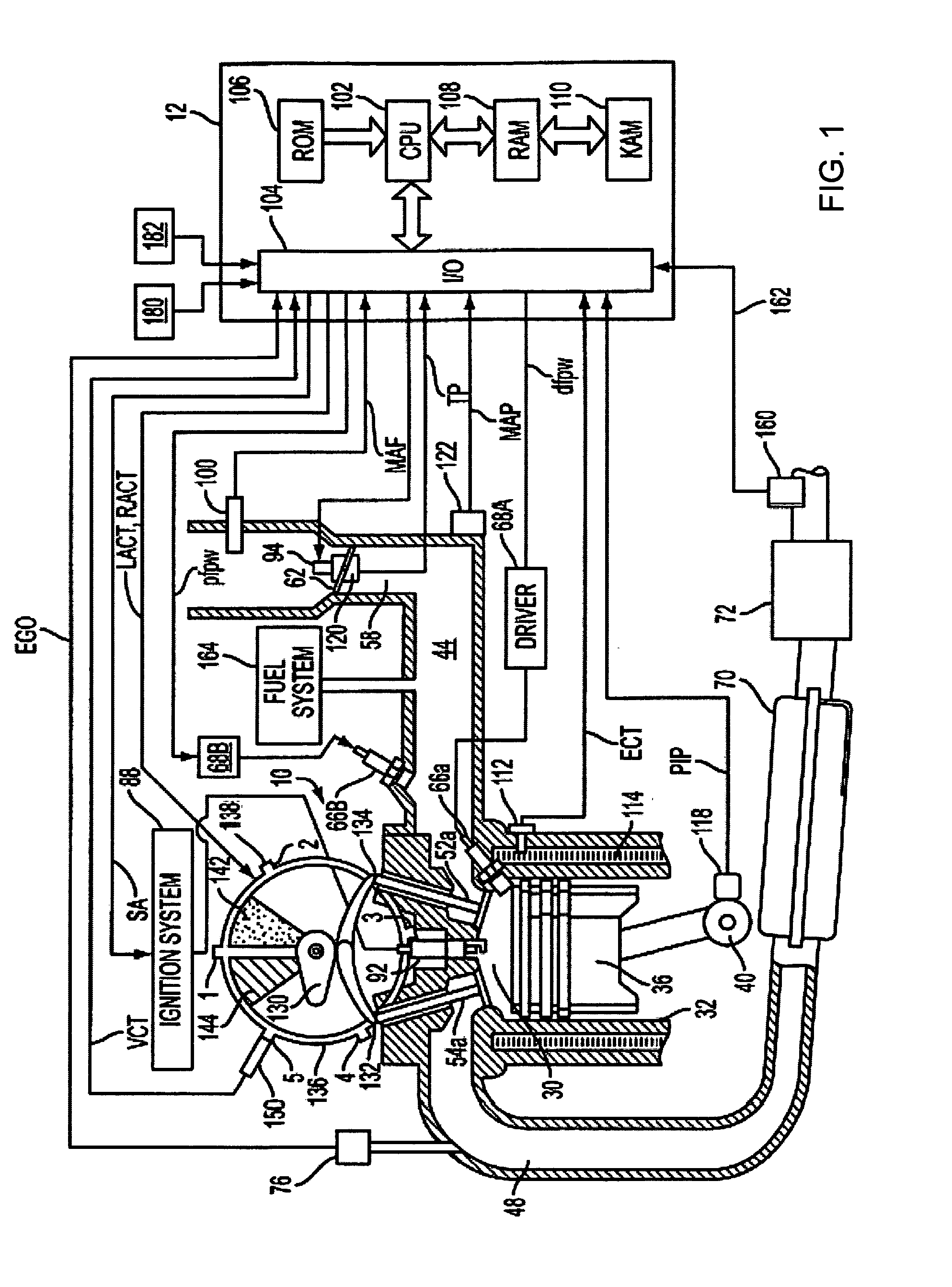
[0017]FIG. 1 shows one cylinder of a multi-cylinder engine, as well as the intake and exhaust path connected to that cylinder. In the embodiment shown in FIG. 1, engine 10 is capable of using two different fuels types, and / or two different injection types. For example, engine 10 may use a hydrocarbon fuel such as gasoline and another substance such as a fluid including an alcohol such as ethanol, methanol, a mixture of gasoline and ethanol (e.g., E85 which is approximately 85% ethanol and 15% gasoline), a mixture of gasoline and methanol (e.g., M85 which is approximately 85% methanol and 15% gasoline), a mixture of an alcohol and water, a mixture of an alcohol, water, and gasoline, etc. As described herein a “substance” may include a liquid or fluid, gas or vapor, solid, or combinations thereof. In some embodiments, a single injector (such as a direct injector) may be used to inject a mixture of two or more fuel and / or fluid types (e.g., gasoline and / or ethanol, methanol, water). Th...


PUM


Abstract

An engine system, comprising of a combustion chamber; a first spark plug configured to perform a spark within the combustion chamber, said first plug configured to have a first heat range; a second spark plug configured to produce a spark within the combustion chamber, said second plug configured to have a second heat range different from said first heat range of said first plug; and a delivery system configured to deliver a hydrocarbon fuel and a fluid including an alcohol to the combustion chamber in varying resulting ratios.

Description

BACKGROUND AND SUMMARY [0001] Engines may use various forms of fuel delivery to provide a desired amount of fuel for combustion in each cylinder. One type of fuel delivery uses a port injector for each cylinder to deliver fuel to respective cylinders. Still another type of fuel delivery uses a direct injector for each cylinder. [0002] Further, engines have been proposed using more than one type of fuel injection. For example, the papers titled “Calculations of Knock Suppression in Highly Turbocharged Gasoline / Ethanol Engines Using Direct Ethanol Injection” and “Direct Injection Ethanol Boosted Gasoline Engine Biofuel Leveraging for Cost Effective Reduction of Oil Dependence and CO2 Emissions” by Heywood et al. are one example. Specifically, the Heywood et al. papers describes directly injecting ethanol to improve charge cooling effects, while relying on port injected gasoline for providing the majority of combusted fuel over a drive cycle. The ethanol provides increased charge cooli...

Claims


Application Information

Patent Timeline
Patent Type & Authority Applications(United States)
IPC IPC(8): F02P15/02F02P5/00F02P15/08
CPCF02B23/104F02B2023/085F02B2075/125F02B2275/16F02D13/0215Y02T10/46F02D41/0025F02D2200/1015F02P5/1527F02P15/02F02P15/08F02D35/027Y02T10/40
Inventor RUSSELL, JOHN D.ANDRI, MICHAEL
Owner FORD GLOBAL TECH LLC
Why Eureka
Try Eureka