Plasma processing apparatus and electrode used therein

a processing apparatus and electrode technology, applied in the direction of welding apparatus, electric discharge tubes, manufacturing tools, etc., can solve the problems of non-uniform distribution of electric field in the radial direction, affecting the uniformity of etching, and plasma density becoming non-uniform, so as to achieve high uniformity and reduce the non-uniform distribution of electric field on the electrode surfa

Active Publication Date: 2007-09-20
TOKYO ELECTRON LTD
View PDF3 Cites 200 Cited by
  • Summary
  • Abstract
  • Description
  • Claims
  • Application Information

AI Technical Summary

Benefits of technology

[0065]In accordance with the present invention, the non-uniformity of electric field distribution on the surface of the electrode can be further reduced over a large area from the center portion of the electrode to the edge portion thereof, and thus the plasma having extremely high uniformity can be generated.

Problems solved by technology

However, in the above-described plasma processing apparatus, since the upper electrode is formed of a conductor or a semiconductor, there are the following disadvantages.
Thus, electric field becomes stronger at the center portion of the electrode, and the distribution of the electric field becomes non-uniform in the radial direction.
When the electric field distribution becomes non-uniform in this manner, the plasma density becomes non-uniform, which affects the uniformity of the etching and so on.
This technology can reduce the non-uniformity of the electric field at the center portion of the electrode, i.e., directly under the hollow portion, compared to the case in which no hollow portion is provided on the rear side of the electrode plate of the upper electrode.
However, there is a limitation in increasing a uniformity of the electric field at the edge portion of the electrode to be the same level as that at the center portion of the electrode.
For this reason, it is difficult to further increase the uniformity of the electric field at the edge portion of the electrode while the uniformity of the electric field at the center portion of the electrode is maintained.

Method used


Image

  • Plasma processing apparatus and electrode used therein
  • Plasma processing apparatus and electrode used therein
  • Plasma processing apparatus and electrode used therein

Examples


first embodiment

[0091](Configuration Example of a Plasma Processing Apparatus )

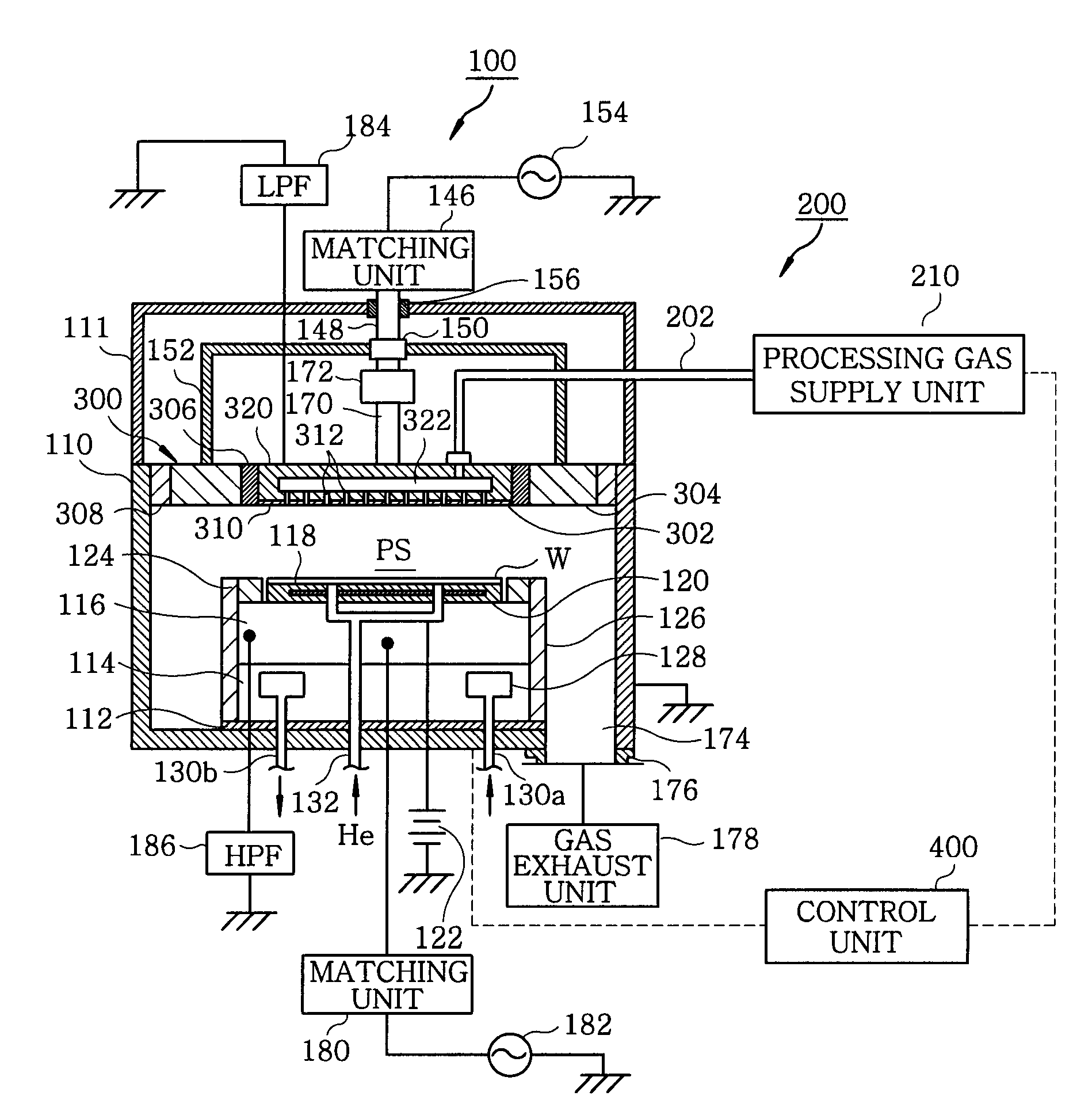
[0092]First, a plasma processing apparatus in accordance with a first embodiment of the present invention will be described with reference to the drawings. FIG. 1 is cross a sectional view showing a schematic configuration of a plasma processing apparatus in accordance with the first embodiment of the present invention. The plasma processing apparatus 100 in FIG. 1 is a parallel plate plasma etching apparatus having an upper electrode for introducing a gas into a processing chamber through a single line.

[0093]The plasma processing apparatus 100 has a processing chamber 110 has a processing vessel having a substantially cylindrical shape. The processing vessel is formed of, e.g., an aluminum alloy, and is electrically grounded. Further, an inner wall of the processing vessel is coated with alumina (Al2O3) or yttria (Y2O3).

[0094]The processing chamber 110 is provided therein with a susceptor 116, which forms a lower electr...

second embodiment

[0161](Configuration Example of Plasma Processing Apparatus )

[0162]Next, a plasma processing apparatus in accordance with a second embodiment of the present invention will be described with reference to the drawings. FIG. 15 is a cross sectional view showing a schematic configuration of a plasma processing apparatus in accordance with the second embodiment of the present invention. A plasma processing apparatus 101 shown in FIG. 15 is a parallel plate plasma etching apparatus having an upper electrode for introducing a gas into a processing chamber via two lines.

[0163]In the second embodiment, an inner upper electrode 302 of the upper electrode 301 is divided into a first and a second gas inlet 350 and 360. The first and the second gas inlet 350 and 360 serve to introduce the gas toward a first and a second region, respectively, on a wafer W mounted on a susceptor 116. The first region is a region, e.g., at the center portion of the wafer W (hereinafter, referred to as “center regio...


PUM

PropertyMeasurementUnit
frequencyaaaaaaaaaa
frequencyaaaaaaaaaa
relative dielectric constantaaaaaaaaaa

Abstract

A plasma processing apparatus performs a specific plasma processing on a target substrate by disposing a first and a second electrode to face each other in a processing chamber, and supplying high-frequency electric power to at least one of the first and the second electrodes to thereby generate a plasma while introducing a processing gas onto the target substrate supported by the second electrode. The electrode for use as the first electrode includes: an electrode plate facing the second electrode; a support for supporting the electrode plate, wherein the support is in contact with a surface of the electrode plate and the surface is opposite to the second electrode; and a dielectric portion, provided on a contact surface of the support with the electrode plate, and having a shape in which a center portion thereof has a height different from that of an edge portion thereof.

Description

FIELD OF THE INVENTION[0001]The present invention relates to a plasma processing apparatus and an electrode used therein.BACKGROUND OF THE INVENTION[0002]In a semiconductor device manufacturing process, plasma processes such as etching, sputtering, CVD (chemical vapor deposition) and the like are mainly performed on a substrate to be processed, e.g., a semiconductor wafer (hereinafter, simply referred to as “wafer”). As plasma processing apparatuses for carrying out such plasma processes, capacitively coupled parallel plate plasma processing apparatuses are widely used.[0003]In this kind of plasma processing apparatus, a pair of parallel plate electrodes (an upper electrode and a lower electrode) is disposed in a chamber, and a processing gas is introduced into the chamber. By applying high-frequency electric power to at least one of the electrodes, a high-frequency electric field is formed between the electrodes and a plasma of the processing gas is generated by means of the high-f...

Claims


Application Information

Patent Timeline
Patent Type & Authority Applications(United States)
IPC IPC(8): B23K9/00
CPCH01J37/32532H01J37/32009
Inventor KOSHIISHI, AKIRASUZUKI, TAKASHI
Owner TOKYO ELECTRON LTD
Why Eureka
Try Eureka