Linear Vibrator

a vibrator and linear technology, applied in the field of linear vibrators, can solve the problems of limitation in miniaturizing the communication apparatus, the external face of the related art vibrator and the external face of the other components, and the difficulty of miniaturizing the related art circular vibrator, so as to increase the vibrating quantity, reduce the manufacturing cost, and increase the reliability of the produ

Inactive Publication Date: 2007-09-20
EM TECHNOLOGY CO LTD
View PDF11 Cites 49 Cited by
  • Summary
  • Abstract
  • Description
  • Claims
  • Application Information

AI Technical Summary

Benefits of technology

[0011]An embodiment of the present invention provides a linear vibrator capable of reducing the manufacturing cost, increas

Problems solved by technology

However, the related art circular vibrator has a difficulty being miniaturized.
Because the circular vibrator and other components are installed together in a communication apparatus, there exist useless spaces between the external face of the related art vibrator and the external faces of the other components.
Thus, there is a limitation in miniaturizing a communication apparatus employing the related art circular vibrator, which has a difficulty in miniaturization.
However, it is difficult to arrange circular components such as a circular vibrating unit in a square shaped case.
Since

Method used


Image

  • Linear Vibrator
  • Linear Vibrator
  • Linear Vibrator

Examples


first embodiment

A First Embodiment

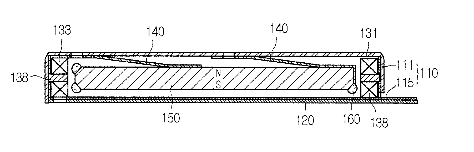
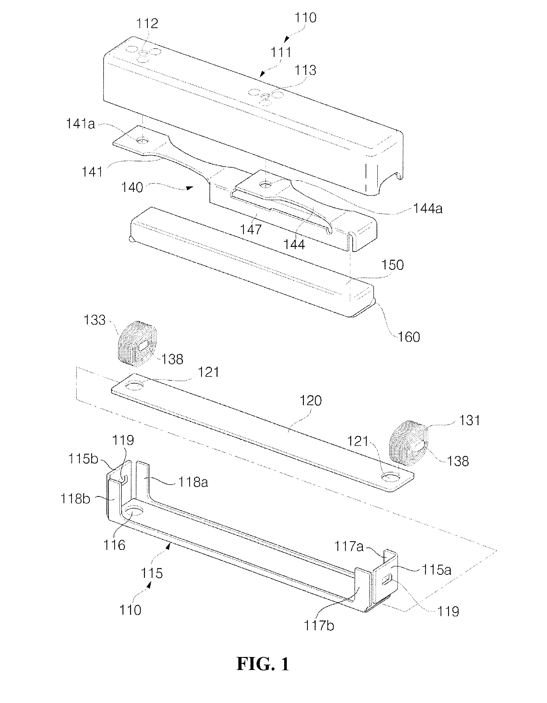
[0026]FIG. 1 is an exploded perspective view illustrating a linear vibrator according to a first embodiment of the present invention. FIG. 2 is a cross-sectional view of the linear vibrator according to the first embodiment of the present invention.

[0027]Referring to FIG. 1, a square shaped case with a predetermined space on the inside can be prepared. The case 110 can include a square shaped upper case portion 111 and a square shaped lower case portion 115 that can be coupled to the upper case portion 111. The upper case portion 111 can have an open bottom side and the lower case portion 115 can have an open top and lengthwise sides.

[0028]The meaning of ‘square shaped’ can be narrowly interpreted as an approximate hexahedron so as to conveniently be arranged inside of a square shaped product such as a communication device. In addition, the meaning of ‘square shaped’ can also be broadly interpreted as a shape having at least one angle shaped side among the case's f...

second embodiment

A Second Embodiment

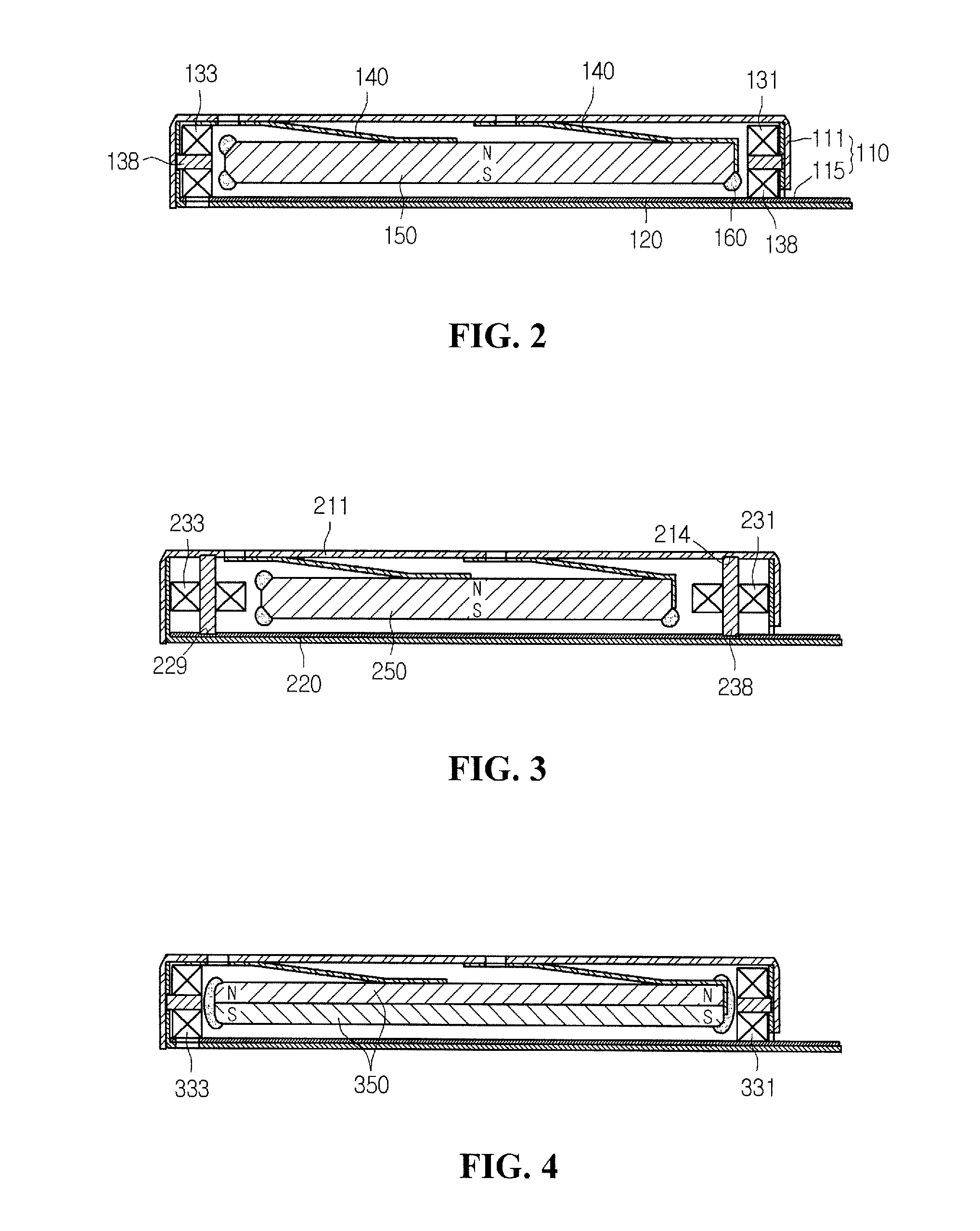
[0070]FIG. 3 is a cross-sectional view of a linear vibrator according to a second embodiment of the present invention.

[0071]Referring to FIG. 3, a linear vibrator according to the second embodiment of the present invention can have a magnet 250 magnetized with different polarities between the upper face and the lower face of the single magnet 250.

[0072]A first and second coil 231 and 233 can be wound in right and left directions.

[0073]In addition, the upper and lower ends of a core 238 can be inserted vertically into a support hole 214 formed at the upper case portion 211 and a support hole 229 formed at the FPCB 220, respectively, so that the core 238 can be supported.

[0074]Because the coils are wound in right and left directions (along a horizontal plane) as compared with the first embodiment, the second embodiment may decrease the magnetic flux which affects the magnet.

[0075]However, because the coils lay down along the lengthwise direction of the case, this em...

third embodiment

A Third Embodiment

[0077]FIG. 4 is a cross-sectional view of a linear vibrator according to a third embodiment of the present invention.

[0078]Referring to FIG. 4, a linear vibrator according to the third embodiment of the present invention can have a magnet 350 magnetized with different polarities between a right side and a left side.

[0079]First and second coils 331 and 333 can be wound in the up and down directions (along a vertical plane). In addition, the linear vibrator according to this embodiment can have two stacked magnets 350.

[0080]This embodiment, in spite of increasing the manufacturing cost as compared to the first embodiment, still can have the advantages described with respect to the first embodiment.

[0081]Furthermore, since a linear vibrator according to this embodiment has ends of the magnet having a maximum polarity in alignment with a coil, it can obtain the maximum electromagnetic force and the maximum magnetic flux density at an adjacent range between the magnet a...


PUM


Abstract

Embodiments of a linear vibrator are provided that are capable of reducing the manufacturing cost, increasing the product reliability and increasing the vibrating quantity. An embodiment of a linear vibrator can include a case formed of an upper case portion and a lower case portion coupled to each other to provide a predetermined inner space; a substrate disposed on an upper surface of the lower case portion; a first coil and a second coil installed at both end parts inside of the case and connected to the substrate; a spring having one side fixed on at least one of the inside faces of the case; and a magnet fixed at another side of the spring and located between the first and second coils inside of the case, where the magnet can vertically vibrate through an interaction with the first and second coils.

Description

CROSS-REFERENCE TO RELATED APPLICATIONS[0001]The present application claims priority under 35 U.S.C. §119 to Korean Patent Application No. 10-2006-0024850, filed Mar. 17, 2006, and Korean Patent Application No. 10-2006-0063383, filed Jul. 6, 2006, which are hereby incorporated by reference in their entirety.BACKGROUND[0002]1. Field of the Invention[0003]The present invention relates to a linear vibrator. A linear vibrator is an apparatus having a vibrating unit which generates a vibration by a reciprocating motion.[0004]2. Description of the Related Art[0005]A related art linear vibrator is provided in a circular shape. The linear vibrator includes a circular case, a coil mounted at the bottom surface of the circular case, a circular vibrating unit contained inside of the circular case, a magnet fixed at the circular vibrating unit, and a spring appending the vibrating unit to the circular case. As for the operation of the vibrator, if an electric power is supplied to the coil, the ...

Claims


Application Information

Patent Timeline
IPC IPC(8): H02K35/00H02K33/00
CPCH02K33/16
Inventor LEE, KAP JIN
Owner EM TECHNOLOGY CO LTD
Why Eureka
Try Eureka