
Spark plug for internal combustion engine and related manufacturing method

a technology for spark plugs and internal combustion engines, which is applied in the direction of spark plugs, spark plugs, basic electric elements, etc., can solve the problems of spark plugs suffering from deformation, spark plugs encountering difficulties in appropriately removing the fuel bridge between the center electrode and the ground electrode, and deterioration of the startability of the internal combustion engine, so as to prevent the fuel bridge and facilitate the formation. , the effect of easy formation

Inactive Publication Date: 2007-09-20
DENSO CORP
View PDF5 Cites 13 Cited by
  • Summary
  • Abstract
  • Description
  • Claims
  • Application Information

AI Technical Summary

Benefits of technology

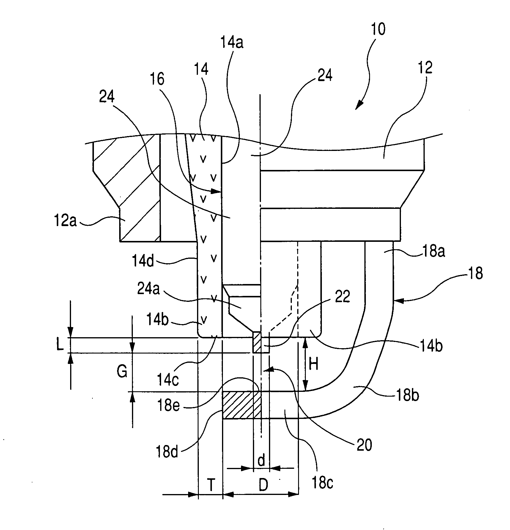
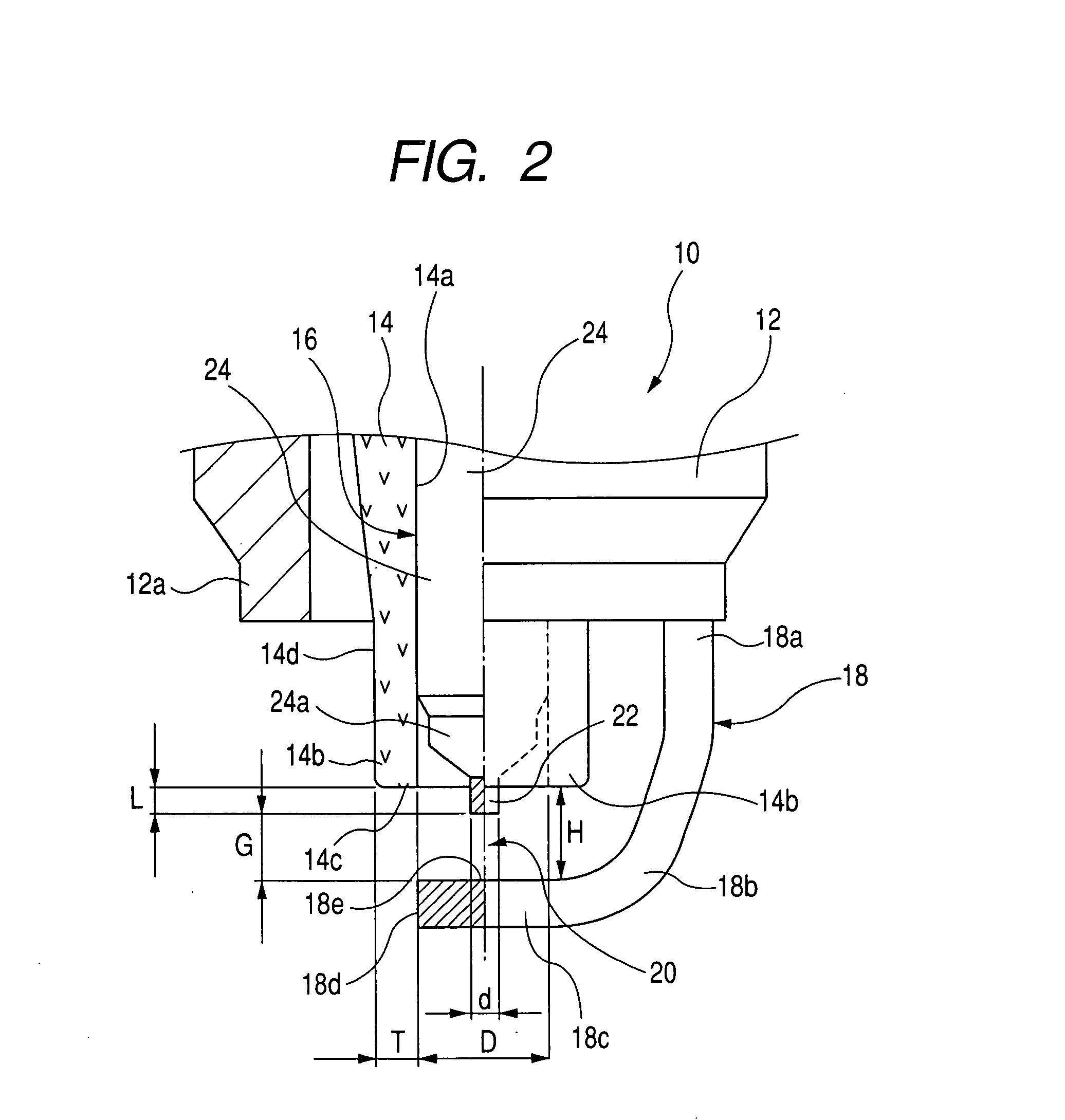
[0018]First, the surface area S1, exposed from the end face of the leading end portion of the ground electrode, of the through-bore of the porcelain insulator as viewed from the distal end of the spark plug, and the total surface area S2 of the through-bore of the porcelain insulator lies under the relationship expressed as S1 / S2≦0.3. This enables the fuel bridge to be easily formed in a pattern so as to cover the entire circumference of the through-bore of the porcelain insulator in an air space between the end face of the leading end portion of the porcelain insulator and the planar surface section of the leading end portion of the ground electrode.
[0019]Further, with the noble metal tip protruding from the end face of the leading end portion of the porcelain insulator in the protruding length L under the relationship expressed as L≦0.6 mm, the fuel bridge becomes liable to easily adhere onto not only an area between the end face of the leading end portion of the porcelain insulator and the planar surface section of the leading end portion of the ground electrode but also the leading end portion of the porcelain insulator.
[0020]Further, with the spark plug of the structured mentioned above, the maximum value Hmax and the minimum value Hmin in distance between the planar surface section of the ground electrode and the end face of the leading end portion of the porcelain insulator lie in the relationship expressed as Hmax / Hmin≦1.3. Such a positional relationship prevents the fuel bridge from being formed in a deviated position dislocated from a correct position, enabling the fuel bridge to be easily formed in an appropriate pattern so as to cover the entire circumference of the through-bore of the porcelain insulator.
[0021]Further, since the wall thickness T of the leading end portion of the porcelain insulator lies in the relationship expressed as T≦0.7 mm, the fuel bridge is prevented from having an excessively increased contact surface area for the leading end portion of the porcelain insulator. This enables the prevention of the fuel bridge from being formed in a disproportionate pattern. Accordingly, the fuel bridge can be formed in an appropriate pattern so as to cover the entire circumference of the through-bore of the porcelain insulator.
[0022]Furthermore, with the leading end of the center electrode having the diameter “d” laying under the relationship expressed as d≦0.6 mm, the fuel bridge is liable to adhere onto not only an area between the center electrode and the ground electrode but also the end face of the leading end portion of the porcelain insulator. This enables the fuel bridge to be formed in an appropriate pattern so as to cover the entire circumference of the through-bore of the porcelain insulator.
[0023]Thus, with the spark plug comprising the component parts arranged under the dimensional relationships set forth above, the spark plug causes the fuel bridge to be easily formed in an appropriate pattern so as to cover the entire circumference of the through-bore of the porcelain insulator. This allows a σπαρκ discharge to easily occur in the inside of the fuel bridge, thereby enabling spark discharge energy to instantaneously remove the fuel bridge.

Problems solved by technology

In any case, issues arise with spark plugs suffering from the occurrence of defacements due to fuel directly injected into combustion chambers.
This results in the occurrence of a fear of deterioration occurring in startability of the internal combustion engine.
However, even with such measure taken on the spark plug, the spark plug encounters a difficulty of appropriately removing the fuel bridge from the center electrode and the ground electrode under circumstances where a large amount of fuel is present for the fuel bridge to be formed like a situation where the engine remains at, for instance, ultracold temperatures or circumstances where fuel has a high viscosity.

Method used


Image

  • Spark plug for internal combustion engine and related manufacturing method
  • Spark plug for internal combustion engine and related manufacturing method
  • Spark plug for internal combustion engine and related manufacturing method

Examples


first embodiment

[0057]A spark plug of a first embodiment according to the present invention is described below in detail with reference to FIG. 1 to 9 of the accompanying drawings.

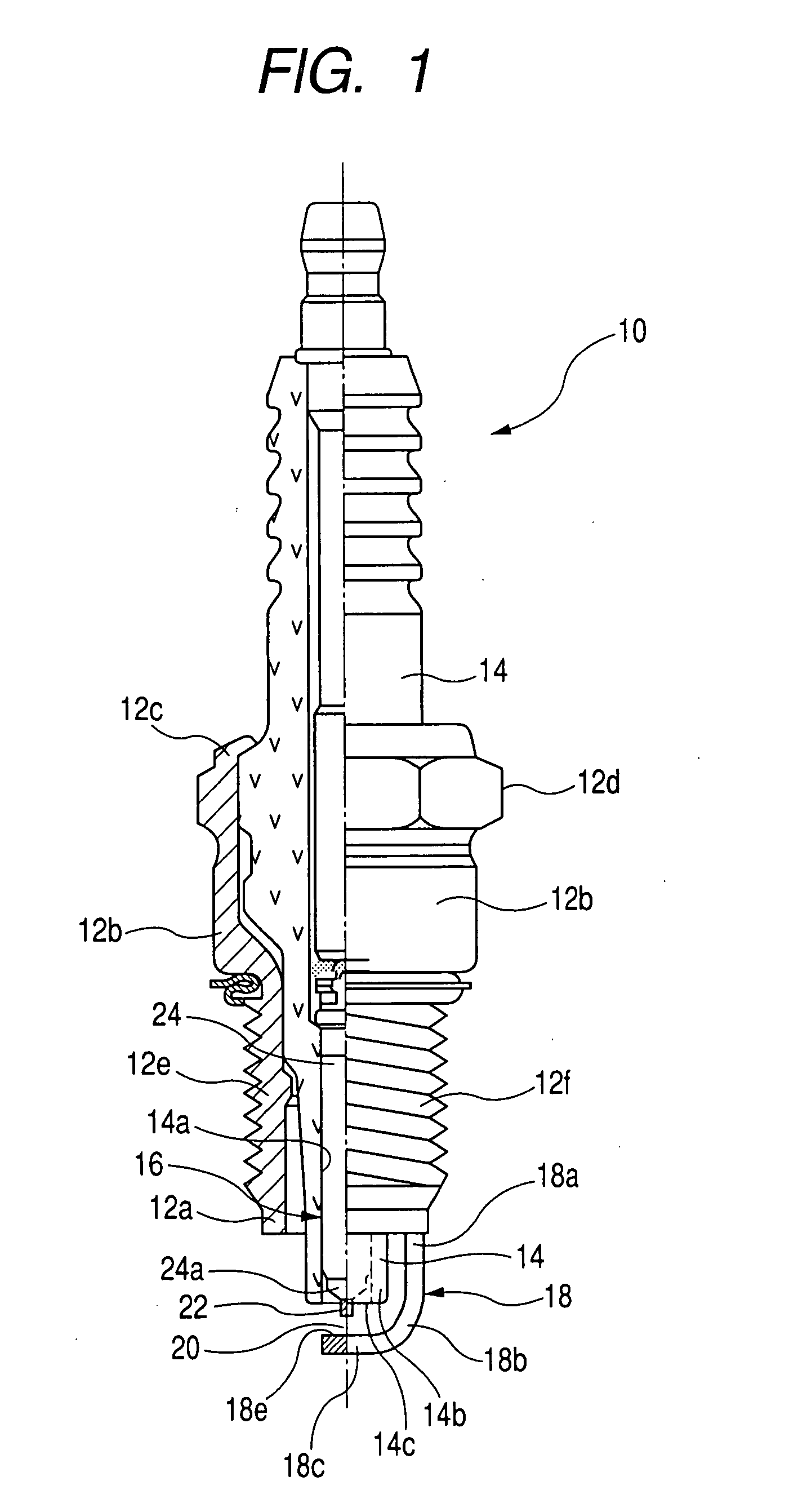
[0058]As shown in FIGS. 1 and 3, the spark plug 10 of the present embodiment comprises a cylindrical metal shell 12, an porcelain insulator 14 fixedly held with the cylindrical metal shell 12 and having a through-bore 14a and a leading end portion 14b extending in a center axis thereof, a center electrode 16 fixedly supported in a through-bore 14a of the porcelain insulator 14 in a center axis thereof, and a ground electrode 18 fixedly bonded to a leading end 12a of the cylindrical metal shell 12 to provide a spark discharge gaps 20 with respect to the center electrode 16.

[0059]The cylindrical metal shell 12 includes an intermediate body 12b, an upper section 12c having an outer circumferential periphery formed in a hexagonal shape to serve as a tool-fitting section 12d, and a lower section 12e having an outer circumferen...

second embodiment

[0092]A spark plug 10A of a second embodiment according to the present invention for an internal combustion engine is described with reference to FIG. 10.

[0093]As shown in FIG. 10, with the spark plug 10A of the present embodiment, a planar surface section 18Ae of a ground electrode 18A has a concaved portion 18f in which a noble metal tip 40 is buried in face-to-face relationship with the noble metal tip 22 of the center electrode 16.

[0094]The noble metal tip 40 may be made of, for instance, an Ir alloy or Pt alloy or the like.

[0095]Further, the noble metal tip 40 has a top surface placed in coplanar relationship with a base material section of the ground electrode 18A. That is, the ground electrode 18A has a ground electrode planar surface section 18Ae on the same plane with the noble metal tip 40.

[0096]The spark plug 10A of the present embodiment has the other same structure as the structure of the spark plug 10 of the first embodiment set forth above.

[0097]With the spark plug 10...

third embodiment

[0099]A spark plug 10B of a third embodiment according to the present invention for an internal combustion engine is described with reference to FIG. 11.

[0100]As shown in FIG. 11, with the spark plug 10B of the present embodiment, a noble metal tip 42 is bonded to a planar surface section 18Be of a ground electrode 18B in face-to-face relationship with the noble metal tip 22 of the center electrode 16.

[0101]The noble metal tip 42 may be made of, for instance, Ir alloy or Pt alloy or the like.

[0102]With the spark plug 10B of the present embodiment, the ground electrode 18B has the ground electrode planar surface section 18Be in an area except for the noble metal tip 42. In addition, the distance H (covering Hmax and Hmin) between the end face 14c of the leading end portion 14b of the porcelain insulator 14 and the ground electrode planar surface section 18Be is a distance measured between the end face 14c of the leading end portion 14b of the porcelain insulator 14 and the ground ele...


PUM


Abstract

A spark plug is disclosed as having a metal shell, a porcelain insulator fixedly secured to the metal shell, a center electrode and a ground electrode providing a spark discharge gap with the center electrode. The porcelain insulator has a through-bore partially exposed from an end face of the ground electrode in a surface area S1, as viewed from a distal end of the spark plug, and having a total surface area S2 falling in the relationship S1 / S2≦0.3. The center electrode protrudes from the porcelain insulator with a protruding length L under the relationship L≦0.6 mm. A minimal value Hmin and a maximal value Hmax in distance between the ground electrode and the end face of the porcelain insulator lies in the relationship Hmax / Hmin≦1.3. Wall thickness T between the through-bore and an outer periphery of the porcelain insulator lies in the relationship T≦0.7 mm.

Description

CROSS REFERENCE TO RELATED APPLICATIONS[0001]This application is based on Japanese Patent Application No. 2006-69246, filed on Mar. 14, 2006, the content of which is hereby incorporated by reference.BACKGROUND OF THE INVENTION[0002]1. Field of the invention[0003]The present invention relates to spark plugs for internal combustion engines and, more particularly, to a spark plug for an internal combustion engine of a motor vehicle or the like.[0004]2. Description of the Related Art[0005]In the related art, attempts have heretofore been made to provide spark plugs as igniting means for internal combustion engines of motor vehicles or the like.[0006]The spark plug generally includes a center electrode and a ground electrode between which a spark discharge gap is provided. Applying a high voltage across the center electrode and the ground electrode allows a spark discharge to take place in the spark discharge gap, thereby igniting an air-fuel mixture.[0007]With the development of automot...

Claims


Application Information

Patent Timeline
IPC IPC(8): H01T13/20
CPCH01T13/20H01T13/39H01T13/36H01T13/32
Inventor YOSHIDA, KOICHI
Owner DENSO CORP
Learn More