Method for driving planar light source device, method for driving color liquid crystal display device assembly, method for driving light emitting diode, and pulse-width modulating method

a technology of color liquid crystal display and light source device, which is applied in the direction of static indicating devices, instruments, optics, etc., can solve the problem of difficult white light white balance adjustmen

Inactive Publication Date: 2007-09-20
SONY CORP
View PDF13 Cites 26 Cited by
  • Summary
  • Abstract
  • Description
  • Claims
  • Application Information

AI Technical Summary

Benefits of technology

[0010] For example, in a case where the value S of a pulse-width modulation output signal is controlled at 8 bits, the value S of the pulse-width modulation output signal is an integer in a range of 0 to 255. Now, assume that SR=SG=SB=3, in order to obtain white light as illuminating light from the planar light source unit. Also, assume that drive of the red, green, and blue LEDs causes the respective LEDs to emit heat, particularly that the Vf characteristic of the red LED varies, that the light output therefrom significantly reduces, and that the white balance of the white light varies.

Problems solved by technology

Accordingly, a relatively large increase in the ON time of the red LED makes an appropriate adjustment of the white balance of white light difficult.

Method used


Image

  • Method for driving planar light source device, method for driving color liquid crystal display device assembly, method for driving light emitting diode, and pulse-width modulating method
  • Method for driving planar light source device, method for driving color liquid crystal display device assembly, method for driving light emitting diode, and pulse-width modulating method
  • Method for driving planar light source device, method for driving color liquid crystal display device assembly, method for driving light emitting diode, and pulse-width modulating method

Examples


first embodiment

[0068] (First Embodiment)

[0069] A first embodiment of the present invention relates a method for driving a planar light source device, a method for driving a color liquid crystal display (LCD) device assembly, a method for driving a light emitting diode (LED), and a pulse-width modulating method.

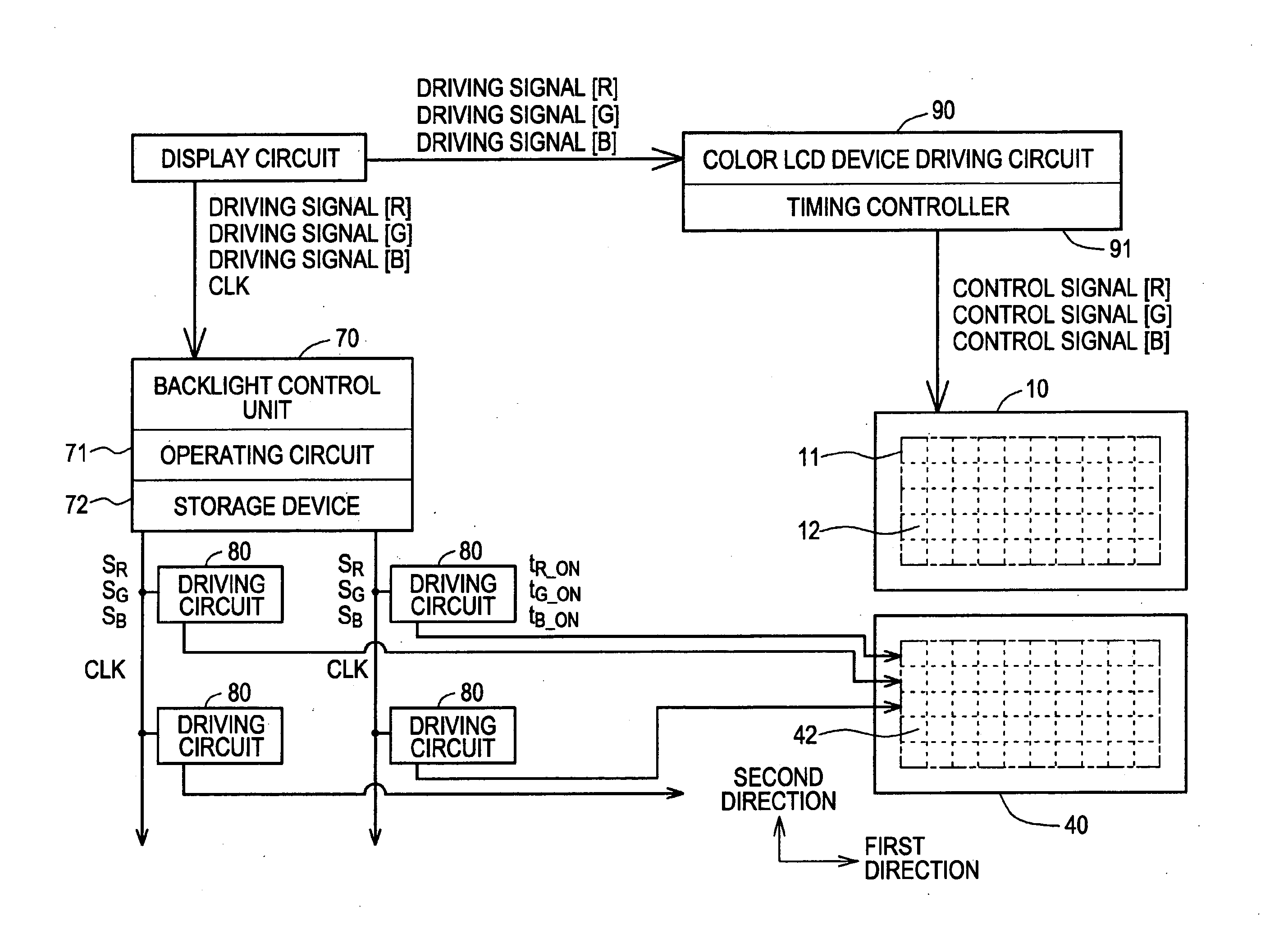
[0070] As shown in a conceptual diagram in FIG. 3, a color LCD device 10 according to the first embodiment includes a display area 11 where M0×N0 pixels are arranged in a two-dimensional matrix pattern (Mo pixels along a first direction and N0 pixels along a second direction). The display area 11 includes P×Q display area units 12, each including a plurality of pixels. More specifically, an HD-TV standard is satisfied as resolution for image display, and the number of pixels M0×N0 (M0, N0) arranged in a two-dimensional matrix pattern is (1920, 1080), for example. The display area 11 (indicated by a dashed-dotted line in FIG. 3) including the pixels arranged in a two-dimensional matrix patte...


PUM

PropertyMeasurementUnit
light transmittanceaaaaaaaaaa
wavelengthaaaaaaaaaa

Abstract

A method for driving a planar light source device is provided. The planar light source device includes (a) a plurality of planar light source units to light a color LCD device from the back, each planar light source unit including a red LED, a green LED, and a blue LED; and (b) a driving circuit to perform ON/OFF control of the red LED, the green LED, and the blue LED included in each planar light source unit on the basis of pulse-width modulation. The method includes adjusting respective pulse-width modulation unit clocks CLR-unit, CLG-Unit, and CLB-Unit in each planar light source unit to long or short by increasing or decreasing the number of frequency division cycles of a system clock in the driving circuit.

Description

CROSS REFERENCES TO RELATED APPLICATIONS [0001] The present invention contains subject matter related to Japanese Patent Application JP 2006-057982 filed in the Japanese Patent Office on Mar. 3, 2006, the entire contents of which are incorporated herein by reference. BACKGROUND OF THE INVENTION [0002] 1. Field of the Invention [0003] The present invention relates to a method for driving a planar light source device, a method for driving a color liquid crystal display (LCD) device assembly, a method for driving a light emitting diode (LED), and a pulse-width modulating method. [0004] 2. Description of the Related Art [0005] In a color LCD device, liquid crystal itself emits no light. Thus, a planar light source device (backlight) is placed on a rear surface of the color LCD device so as to directly light the color LCD device. In the color LCD device, each pixel includes three sub-pixels: a red light emitting sub-pixel; a green light emitting sub-pixel; and a blue light emitting sub-p...

Claims


Application Information

Patent Timeline
Patent Type & Authority Applications(United States)
IPC IPC(8): G09G3/36G02F1/133G02F1/13357G09G3/20G09G3/34H01L33/00H05B37/02
CPCG09G3/2014G09G2360/145G09G2300/0452G09G3/3413
Inventor KOJIMA, KAZUO
Owner SONY CORP
Why Eureka
Try Eureka