
Light source device, optical scanning device, and image forming apparatus

a light source device and scanning device technology, applied in the field of light source devices, optical scanning devices, image forming apparatus, can solve the problems of large scanning line curvature, difficult cost reduction and miniaturization of optical scanning devices, and high cost of polygon mirrors compared to other optical elements that constitute optical scanning devices

Inactive Publication Date: 2007-09-20
RICOH KK
View PDF1 Cites 25 Cited by
  • Summary
  • Abstract
  • Description
  • Claims
  • Application Information

AI Technical Summary

Benefits of technology

[0028]It is an object of the present invention to at least

Problems solved by technology

In general, a polygon mirror costs high compared to other optical elements that constitute an optical scanning device.
For such reasons, cost reduction and miniaturization of the optical scanning device are difficult.
However, in the oblique-incidence optical system, large scanning line curvature may occur.
The light beams are obliquely incident on a scanning lens, which increases wavefront aberration and deteriorates optical performance at a peripheral image height.
Thus, a beam-spot diameter increases, which lowers image quality.
While the conventional technologies are capable of correcting the scanning line curvature, the wavefront aberration is not sufficiently corrected.
However, it is difficult to reduce scanning line curvature and wavefront aberration caused by the other light beams.
Because of curvature of a lens in the sub-scanning direction, light beams incident on the lens may shift or tilt in the sub-scanning direction due to an error that occurs when the optical elements are processed or assembled.
Accordingly, prevention of color difference that is originally thought to be possible cannot be achieved.
It is also difficult to prevent wavefront aberration and obtain a preferred beam-spot diameter stably because the angles of the beams on the curved surface vary and thus the amount of skew of the light beams changes.
Accordingly, the image quality deteriorates.
However, the accurate processing and assembly increase the cost of the optical elements and assembly time.
When the angles of incidence of the light beams on the deflecting-reflecting surface are increased in the oblique-incidence optical system, various types of aberrations are increased, which deteriorates optical performance.
However, smaller angles of incidence make it difficult to cause each of light beams to be directed to a corresponding one of scanned surfaces.
However, when the angles of incidence are changed, some of the light beams may not precisely pass through or be deflected by the optical elements, and the beam-spot diameter increases.
Even when the light beams precisely pass through or are deflected by the optical elements, the beam-spot diameter changes, and preferred beam spots cannot be obtained.
However, the light source device cannot prevent the change in angles of incidence due to the processing error or assembly error.
However, in this case, attachment or adjustment of the light source device is complicated, and the time required for adjustment increases.

Method used


Image

  • Light source device, optical scanning device, and image forming apparatus
  • Light source device, optical scanning device, and image forming apparatus
  • Light source device, optical scanning device, and image forming apparatus

Examples


Embodiment Construction

[0044]Exemplary embodiments of the present invention are described below with reference to the accompanying drawings.

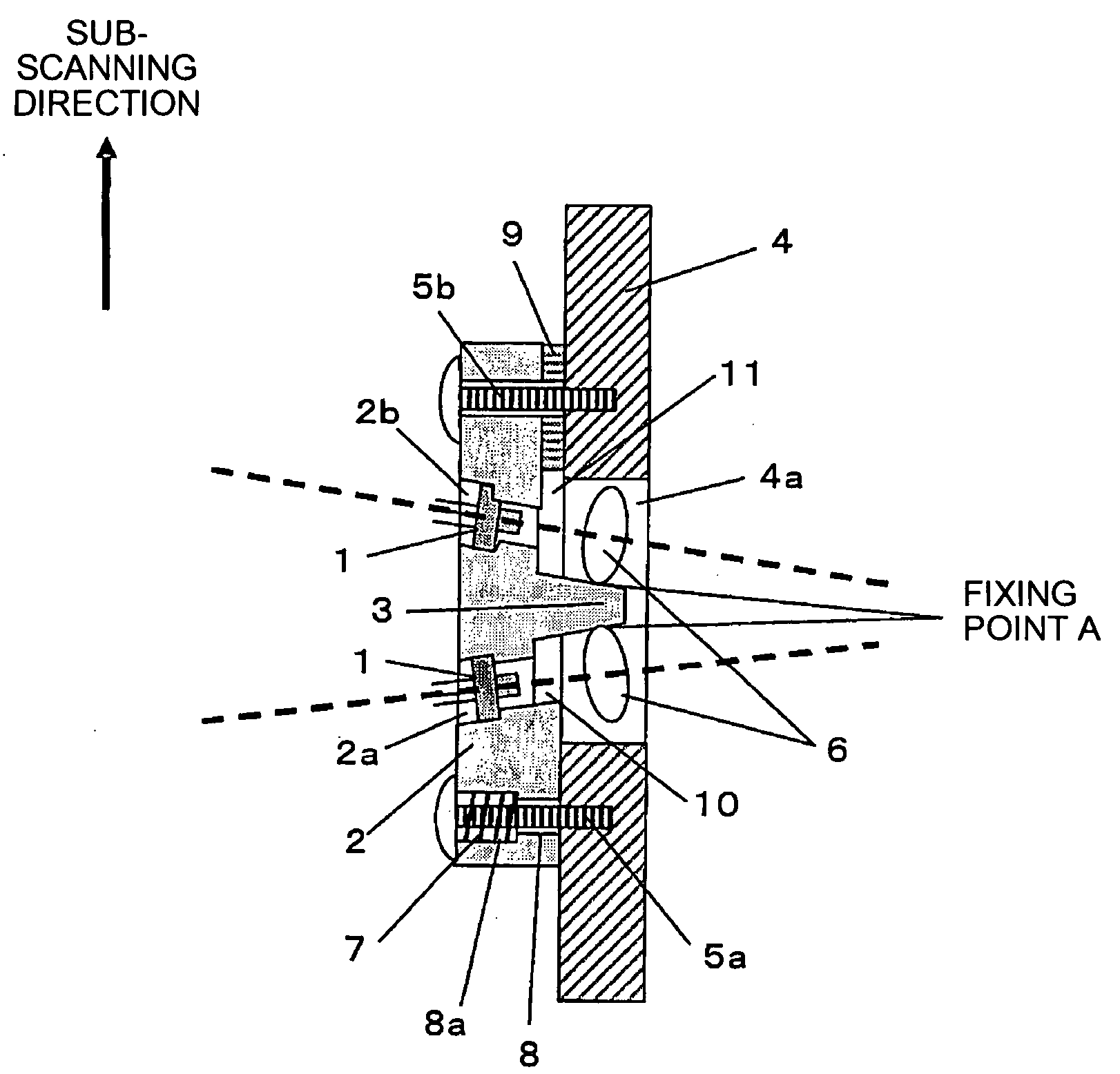
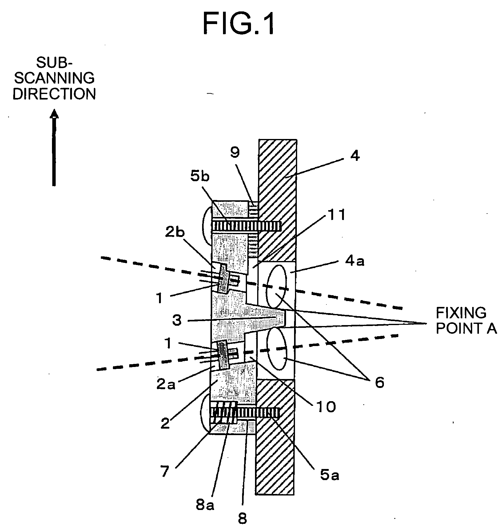
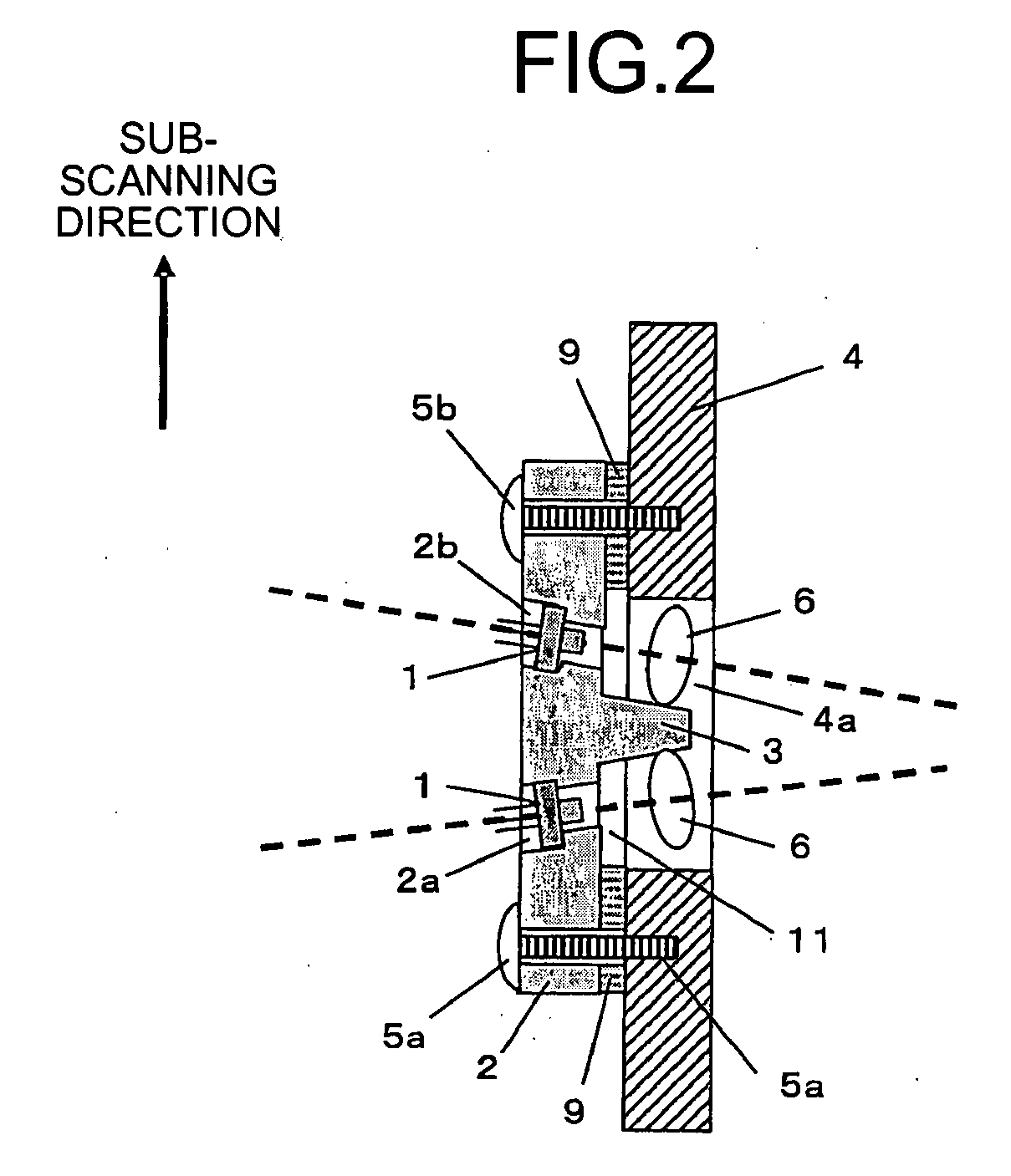
[0045]FIG. 1 is a cross section of a light source device according to an embodiment of the present invention. The light source device includes semiconductor lasers 1, a light-source holding member 2, a lens fixing member 3, a platy attachment member 4, a first screw 5a and a second screw 5b, and coupling lenses 6. The light-source holding member 2 is made of aluminum die-cast, and includes through holes 2a and 2b to hold the semiconductor lasers 1 arranged in parallel to a sub-scanning direction. The lens fixing member 3 is integrally formed with the light-source holding member 2. The attachment member 4 includes a hole 4a. The first screw 5a and the second screw 5b are separated in the sub-scanning direction, and fix the light-source holding member 2 to the attachment member 4. The coupling lenses 6 are arranged in the hole 4a, and fixed to the lens fixing member 3 t...


PUM


Abstract

A light-source holding member that holds semiconductor lasers along the sub-scanning direction is fixed to an attachment member at two points with first and second screws. An elastic member is interposed between the light-source holding member and the attachment member to urge the second screw upwards. The light-source holding member can be tilted with respect to the sub-scanning direction depending on the fastening force of the second screw. By adjusting the fastening force of the second screw, angles of light beams emitted from the semiconductor lasers are adjustable.

Description

CROSS-REFERENCE TO RELATED APPLICATIONS[0001]The present document incorporates by reference the entire contents of Japanese priority document, 2006-070534 filed in Japan on Mar. 15, 2006.BACKGROUND OF THE INVENTION[0002]1. Field of the Invention[0003]The present invention relates to a light source device, an optical scanning device that includes the light source device, and an image forming apparatus that includes the optical scanning device.[0004]2. Description of the Related Art[0005]Optical scanning devices relating to laser printers or the like are widely known. Generally, in such an optical scanning device, a light beams emitted from a light source are deflected by a deflector. Through an optical scanning and imaging system such as an fθ lens, the light beams are directed to and focused on a surface to be scanned (hereinafter, “scanned surface”). Accordingly, a light spot is formed on the surface to scan the surface in the main-scanning direction. The surface is, for example, a...

Claims


Application Information

Patent Timeline
IPC IPC(8): B41J15/14
CPCB41J2/473
Inventor MIYATAKE, NAOKI
Owner RICOH KK
Learn More