
Wound capacitor having a thermal disconnect at a hot spot

Inactive Publication Date: 2007-09-20
ELECTRONICS CONCEPTS
View PDF30 Cites 9 Cited by
  • Summary
  • Abstract
  • Description
  • Claims
  • Application Information

AI Technical Summary

Benefits of technology

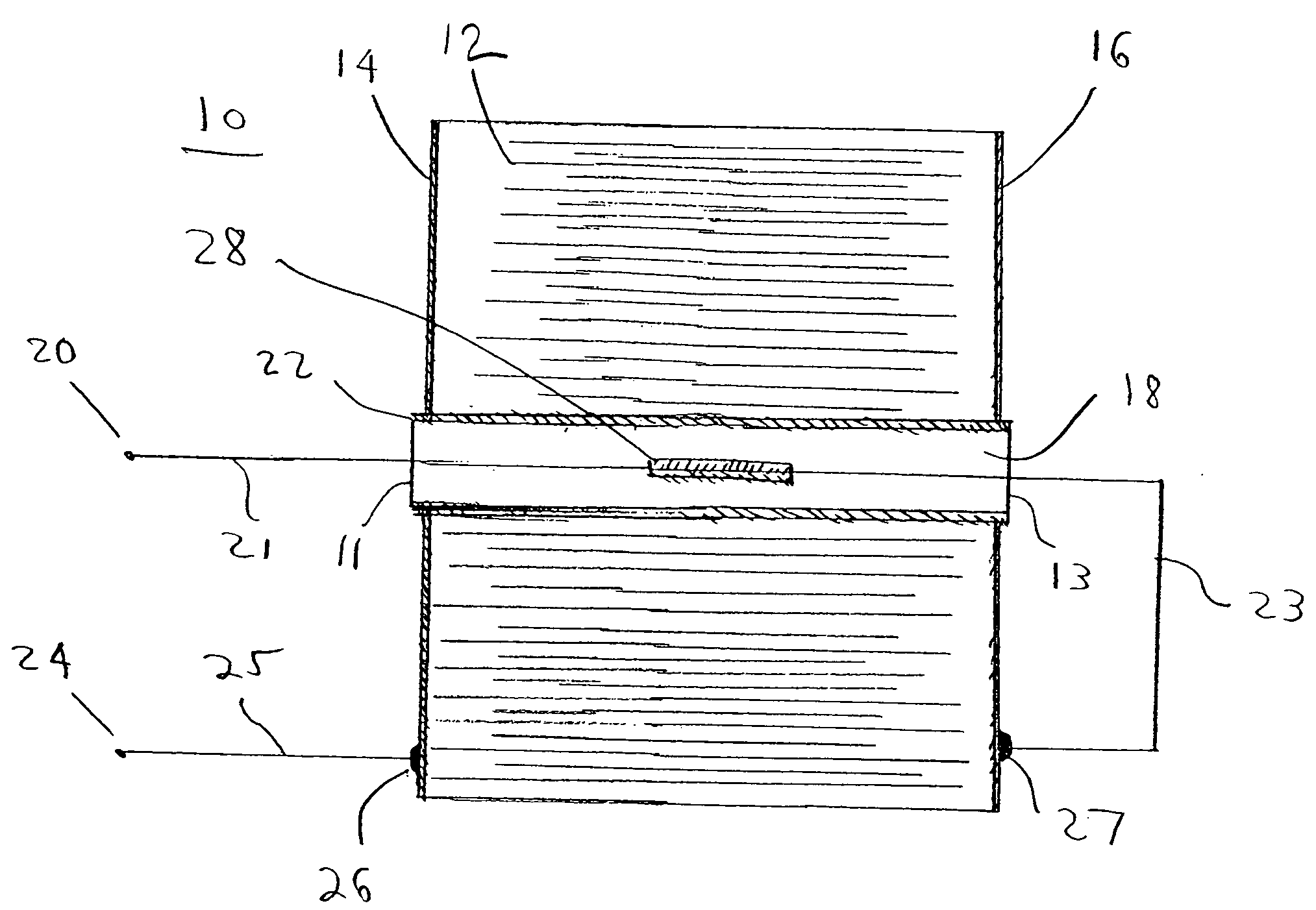
[0010]To meet this and other needs, and in view of its purposes, the present invention provides a capacitor having a large current carrying capacity including (a) a hollow core formed by a non-conducting tubular section, (b) a capacitor winding wrapped around the tubular section, and (c) a thermal cutoff device disposed within the hollow core. The thermal cutoff device is configured to sense a predetermined temperature level within the hollow core and disable

Problems solved by technology

In large current applications (for example 7 amperes to 30 amperes), this thermal energy can be quite large and may lead to the deterioration of the capacitor.
In some applications the thermal energy may even lead to an explosion.
Additionally, thermal energy may be increased if the capacitor is hermetically sealed, because the hermetic sealing may make it more difficult for the heat to be transferred to the exterior of the capacitor and be dissipated.

Method used


Image

  • Wound capacitor having a thermal disconnect at a hot spot
  • Wound capacitor having a thermal disconnect at a hot spot
  • Wound capacitor having a thermal disconnect at a hot spot

Examples


Embodiment Construction

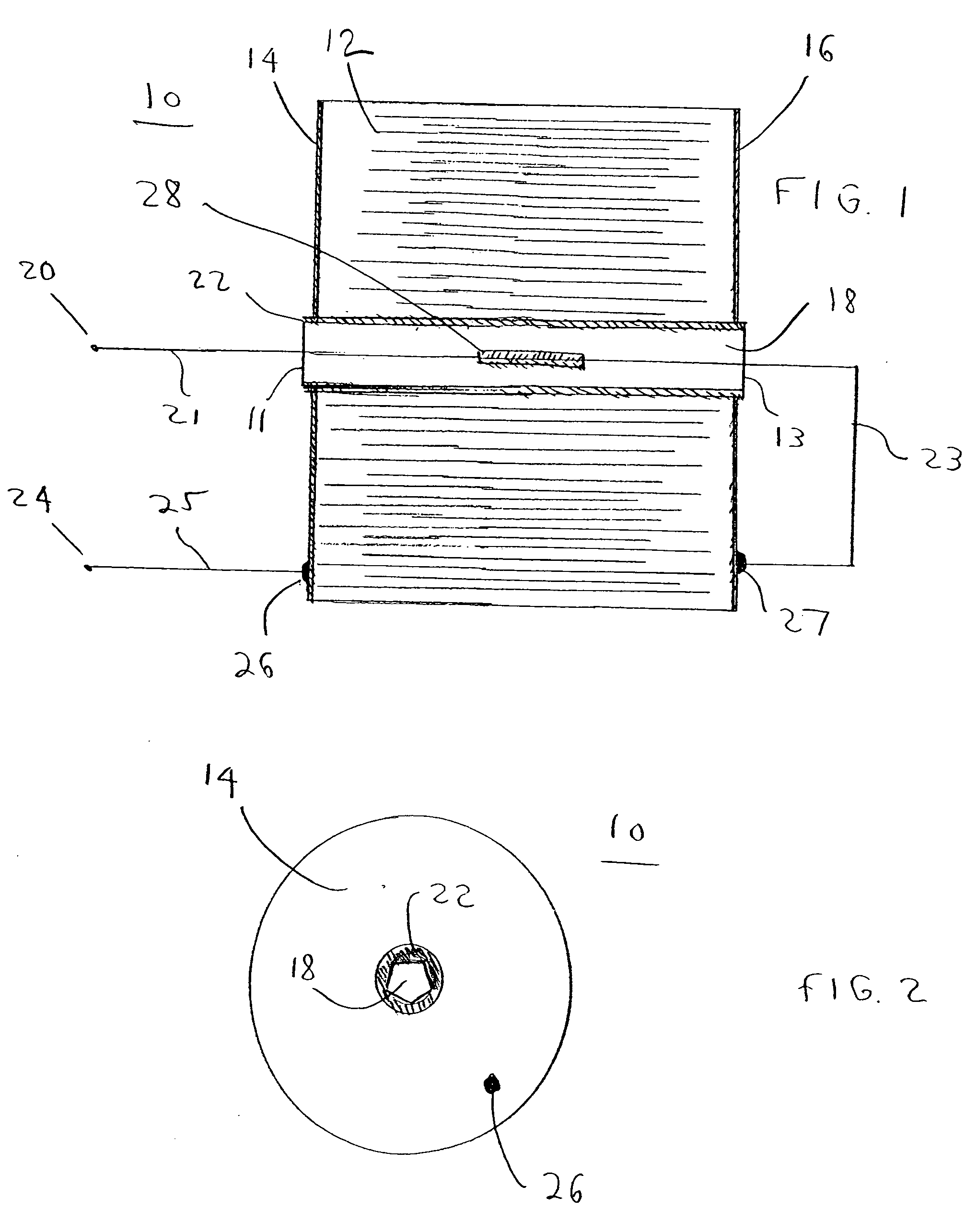
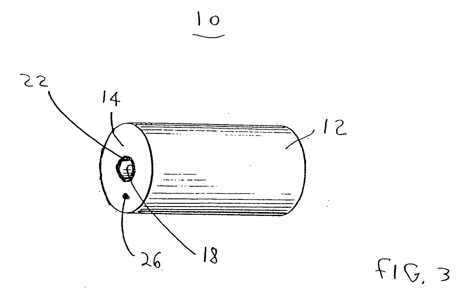
[0029]Referring now to the FIGS. 1, 2 and 3 there is shown a high current carrying capacitor, generally designated as 10. Capacitor 10 includes hollow core 18 surrounded by capacitor winding 12, whereby thermal energy produced within capacitor winding 12, resulting from electrical current passing through winding 12, is transmitted to hollow core 18. As shown, hollow core 18 is formed by non-conducting tubular section 22 which extends slightly beyond the ends of capacitor winding 12 and includes thermal energy from capacitor winding 12. At opposite ends of capacitor winding 12 are two metallization layers 14 and 16.

[0030]It will be appreciated that on completion of winding 12 of the capacitor roll, the ends of capacitor winding 12 may be sprayed with a high velocity mixture of compressed air and molten fine particles of tin produced from an electric arc gun. This spray forms opposing metallization layers 14 and 16, which may be considered electrically the same as opposing first and s...


PUM


Abstract

A capacitor having a large current carrying capacity includes a hollow core formed by a non-conducting tubular section, and a capacitor winding wrapped around the tubular section. A thermal cutoff device is disposed within the hollow core. The thermal cutoff device is configured to sense a predetermined temperature level within the hollow core and disable the current carrying capacity of the capacitor. The thermal cutoff device is disposed at a geometric center of the capacitor winding, which is also the hot spot of the capacitor winding. The thermal cutoff device includes first and second conductors electrically connected to each other with a predetermined solder alloy. The first conductor includes a cross-sectional portion that is attached to the second conductor. The cross-sectional portion is subjected to a springing force in a lateral direction away from the second conductor. Upon melting of the solder alloy, the springing force moves the cross-sectional portion away from the second conductor, thereby disabling the current carrying capacity of the capacitor.

Description

CROSS REFERENCE TO RELATED APPLICATIONS[0001]This application claims priority to U.S. Provisional Patent Application Ser. No. 60 / 782,469 filed Mar. 15, 2006.TECHNICAL FIELD[0002]The present invention relates, in general, to a wound metallized film capacitor. More specifically, the present invention relates to a wound film capacitor having a thermal disconnect device disposed at a hot spot of the capacitor.BACKGROUND OF THE INVENTION[0003]A standard metallized film capacitor widely known in the art is the wound capacitor. Wound capacitors are constructed by sandwiching a dielectric film such as polycarbonate, polypropylene or polyester film, between metal electrodes (e.g., vapor deposited metal film). Once formed, the combination dielectric / metal material is wound to form a capacitor. Some specific examples of wound capacitors are found in the following: U.S. Pat. No. 4,719,539 (Lavene), U.S. Pat. No. 4,685,026 (Lavene), and U.S. Pat. No. 5,614,111 (Lavene). Each of these U.S. patent...

Claims


Application Information

Patent Timeline
IPC IPC(8): H01G9/10
CPCH01G2/18H01G2/16
Inventor LAVENE, BERNARDCURTO, DAVIDSCHACH, ALAN
Owner ELECTRONICS CONCEPTS
Learn More