
Cooperative relay networks using rateless codes

a cooperative relay network and rateless code technology, applied in data switching networks, site diversity, instruments, etc., can solve the problems of waste of channel noise, unreliable communication, waste of transmission power, etc., to reduce the total transmission time, reduce the total power consumption, and reduce the transmission time or total power consumption. small

Inactive Publication Date: 2007-09-20
MITSUBISHI ELECTRIC RES LAB INC
View PDF6 Cites 92 Cited by
  • Summary
  • Abstract
  • Description
  • Claims
  • Application Information

AI Technical Summary

Benefits of technology

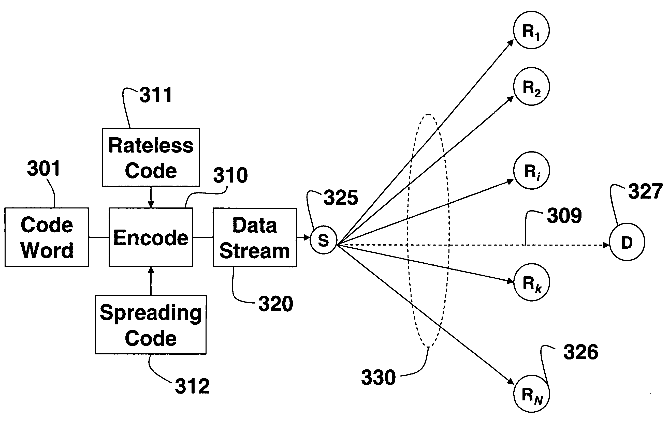
[0021] By using rateless codes, the total transmission time, as well as possibly the total power required for transmitting code words from the source node to the destination node, is reduced.
[0022] In one embodiment of the invention, the source stops transmitting and the relay nodes start transmitting after a predetermined number of relay nodes have successfully decoded the code word. The method can optimize the number to make either the transmission time or the total power consumption as small as possible.
[0023] In an alternative embodiment, each relay node starts transmitting to the destination node as soon as it has decoded the code word, independent of the state of the other relay nodes. This further reduces the total power consumption because the transmission by the relay nodes can be received by other relay nodes and assists the other relay nodes that are still in receive mode in decoding their code words.

Problems solved by technology

However, they do not consider the cost of acquiring the CSI.
In such situations, using a standard block error-correcting code that is too weak for the channel noise, leads to unreliable communication, while using a block error-correcting code that is too strong for the channel noise is wasteful.

Method used


Image

  • Cooperative relay networks using rateless codes
  • Cooperative relay networks using rateless codes
  • Cooperative relay networks using rateless codes

Examples


Embodiment Construction

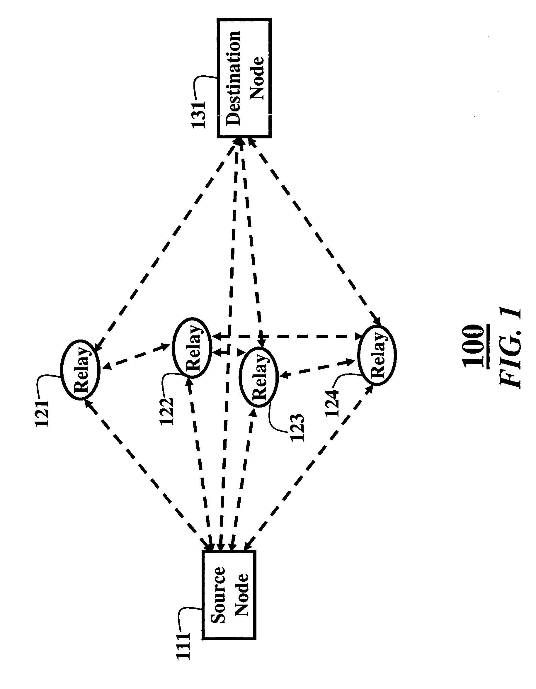
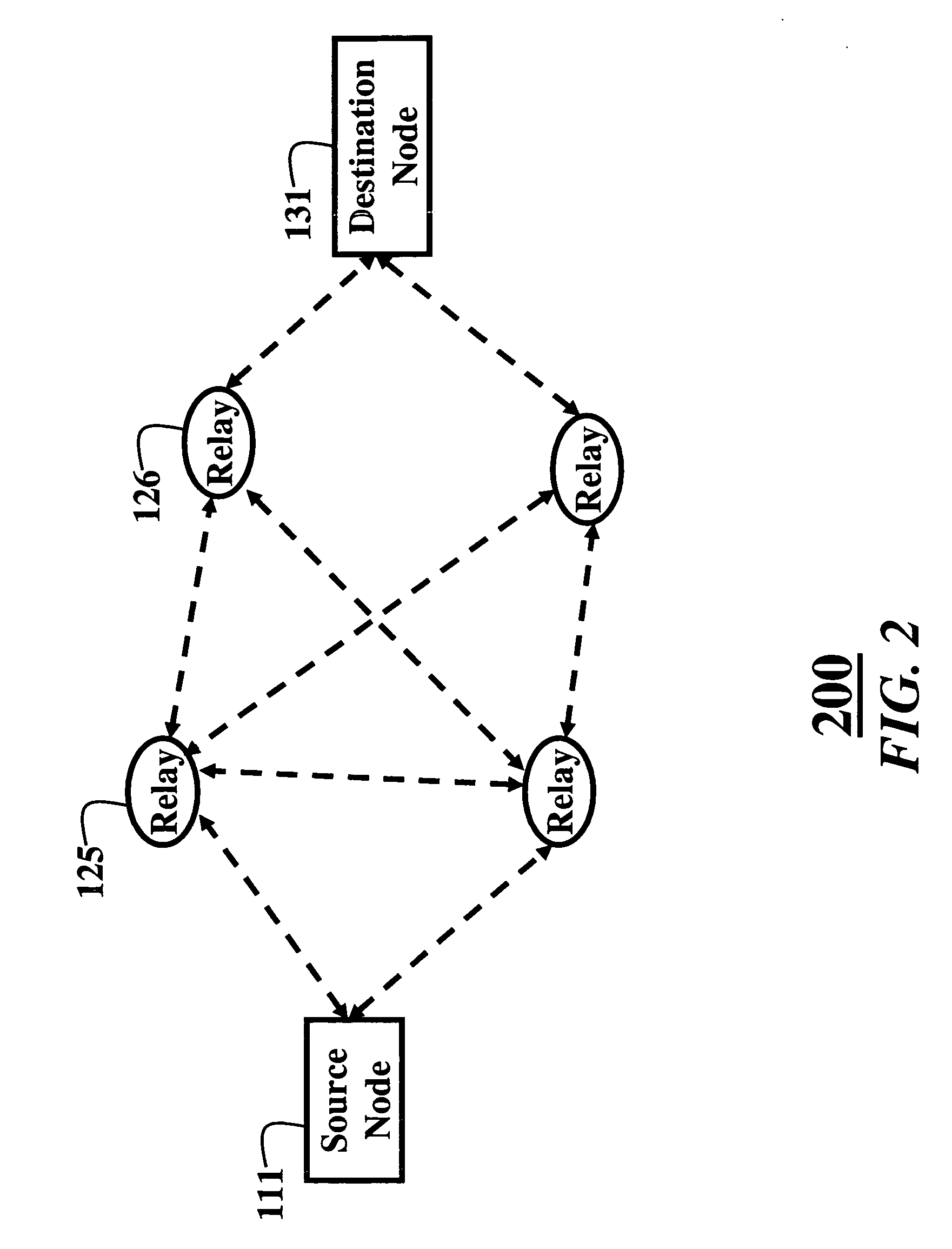
[0029]FIGS. 1 and 2 show cooperative relay networks 100 and 200 according to embodiments of our invention. The cooperative relay network 100 includes a source node 111, a set of N relay nodes 121-124, and a destination node 131, i.e., source, relays, and destination, respectively. It should also be understood, that the embodiments of the invention can also by used with multiple relay ‘hops’ as shown in FIG. 2. In this case, relay 125 also acts as a ‘source’ for an ‘intermediate’ relay 126. This scheme can be extended to additional hops. The following description refers to the case of a single hop, but all the below-described methods are equally valid for the case that includes intermediate relays.

[0030] It is desired to minimize either transmission time and / or power consumption in cooperative relay networks while sending data packets, possibly subject to constraints with respect to outage, where outage is defined as not having a successful transmission within a predetermined time o...


PUM


Abstract

A system and method for communicating information in a wireless cooperative relay network of nodes, the nodes including a source, a set of relays, and a destination. The source broadcasts a code word encoded as a data stream using a rateless code. The relays receive the data stream, decode the data stream to recover the code word, and reencode and transmit the recovered code word as the data stream with the rateless code. The destination receives and decodes the reencoded data streams to recover the code word.

Description

FIELD OF THE INVENTION [0001] The invention relates generally to wireless communications networks, and more particularly to communicating in cooperative relay networks and multi-hop networks. BACKGROUND OF THE INVENTION [0002] Cooperative Relay Networks [0003] In conventional relay networks, data packets are transmitted from a source node to a destination node via a single path with, perhaps, multiple serial hops through relay nodes. [0004] In a cooperative relay networks, wireless nodes cooperate with each other in transmitting data packets in parallel. By exploiting the broadcast nature of a wireless channel to reach multiple relay nodes concurrently, and by enabling the relay nodes to cooperate, it is possible to reduce power consumption in delivering a packet from the source to the destination. This can also significantly increase gains in overall throughput and power efficiency, A. Nosratinia, T. Hunter and A. Hedayat, “Cooperative communication in wireless networks,” IEEE Comm...

Claims


Application Information

Patent Timeline
IPC IPC(8): H04L12/56
CPCH04B7/026H04B7/15592H04W52/46H04L1/0618H04L2001/0092H04L1/06H04L2001/0097
Inventor MOLISCH, ANDREASMEHTA, NEELESHYEDIDIA, JONATHANZHANG, JINYUN
Owner MITSUBISHI ELECTRIC RES LAB INC
Learn More