
Video coding method, video coding apparatus and video coding program

a video coding and video coding technology, applied in the field of video coding methods, video coding apparatuses and video coding programs, can solve the problems of shortening the number of ref_idx, failure to generate a motion vector of a temporal direct mode, and the risk of being unable to effectively utilize the improvement of compression efficiency by adopting the temporal direct mode. to achieve the effect of improving compression efficiency

Inactive Publication Date: 2007-09-20
FUJITSU LTD
View PDF4 Cites 24 Cited by
  • Summary
  • Abstract
  • Description
  • Claims
  • Application Information

AI Technical Summary

Benefits of technology

The present invention aims to improve video coding efficiency by using a direct mode without compromising image quality. It achieves this by selecting the direct mode based on a variable selection criterion and coding the video blocks accordingly. The invention also addresses the issue of selecting a temporal direct mode when a B-Picture is used as a reference. The method includes a means for judging whether or not a List0 and a List1 exist biased to the forward or backward direction and suppressing the temporal direct mode if both lists exist in the same direction. The technical effects of the invention include improved compression efficiency, prediction efficiency, and coding efficiency.

Problems solved by technology

Meanwhile, in the case of a Field structuring carrying out a coding by the unit of a field of an input video image, the common method of taking two reference pictures each in the forward and backward directions causes a shortage in the number of ref_idx, resulting in a failure to generate a motion vector of a temporal direct mode.
The technique disclosed by the patent document 1, however, discards the temporal direct mode in the case of being unable to carry out the scaling process, and therefore is faced with a risk of being unable to effectively utilize an improvement of compression efficiency by adopting the temporal direct mode.

Method used


Image

  • Video coding method, video coding apparatus and video coding program
  • Video coding method, video coding apparatus and video coding program
  • Video coding method, video coding apparatus and video coding program

Examples


example 1

CODING CONTROL EXAMPLE 1

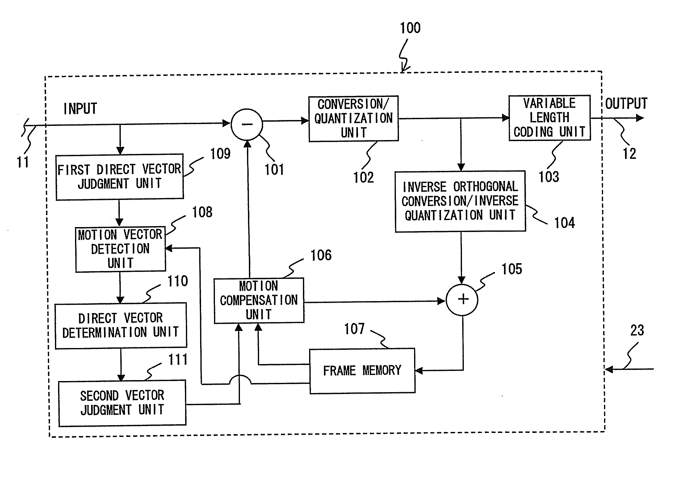
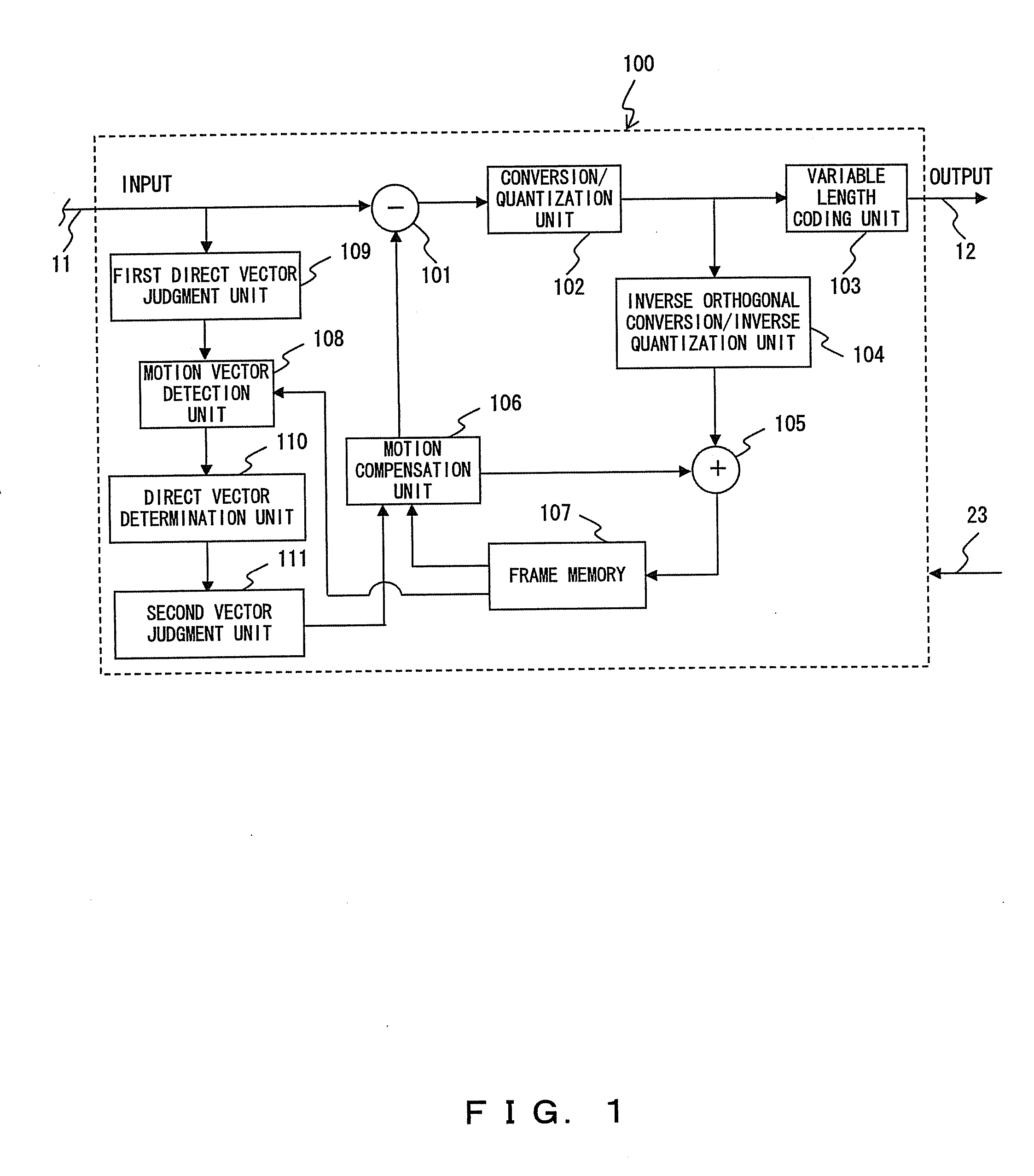
[0080] The next is a detailed description of an example operation at the first direct vector judgment unit 109 in the above described step 203.

[0081] The first direct vector judgment unit 109 changes the mvCol of a motion vector of a direct mode by the unit of picture as described later in order to improve a prediction efficiency, thereby avoiding problems such as a degradation of accuracy and an inability of selecting the temporal direct mode, et cetera, in the case of a Field structure (i.e., a jump scan image).

[0082] The following operation is required only for a Bottom field of an I- and a P-Pictures in the case of a Field structure.

[0083]FIG. 11 shows the case of applying the temporal direct mode if each picture 11a of the video data 11 has a Field structure constituted by a top field 11b (i.e., a field including scanning lines of odd numbers) and a Bottom field 11c (i.e., a field including scanning lines of even numbers).

[0084] The coding sequence o...

example 2

CODING CONTROL EXAMPLE 2

[0098] In the coding control example 2, the description is of a countermeasure for not causing an occurrence of a direct mode. Also the case of the coding control example 2 is a countermeasure in the case of direct vectors 0 and 1 being generated by an external division of the mvCol as shown in FIG. 11.

[0099] In FIG. 11, the mvCol of the co-location Macro Block of a Col-Pic points at a opposite parity (i.e., a Top Field 11b) within the same frame, this Macro Block, however, actually is also capable of generating a motion vector by referring to a co-location Macro Block of a Field (whose coding sequence=1) of Ref_idx of List0. In such a case, calculated direct vectors 0 and 1 per se are generated by an internal division of the mvCol, and therefore do not create a problem in terms of a vector accuracy.

[0100] Accordingly, an adopted countermeasure is not to let a direct mode occur only in the case of a mvCol existing biased toward the past or future temporal d...

example 3

CODING CONTROL EXAMPLE 3

[0106] A coding control example 3 is configured to make it difficult to select a direct mode if a degradation of accuracy is predicted as in the case of FIG. 11 in judging as to which predictive coding mode, i.e., a direct mode or another predictive coding mode, is to be selected.

[0107] That is, the above described coding control example 2 is configured to control so as not to select a direct mode at all in a case applicable to a condition where there is a risk of a degradation of accuracy as exemplified by FIG. 11.

[0108] Comparably, the present coding control example 3 is configured to analyze a condition quantitatively in greater details and applies a weighting to criteria for selecting a direct mode so as to make it difficult to select it in a case applicable to the condition where there is a risk of a degradation of accuracy as exemplified by FIG. 11.

[0109] Actual predictive modes of a Macro Block include various methods for predicting at a Macro Block...


PUM


Abstract

The present invention provides a video coding method which includes, as one of a plurality of coding modes, a direct mode generating a piece of motion information of each of Macro Blocks, which are obtained by dividing a first picture, by predicting from motion information of a coded Macro Block of other plurality of second pictures, including: a first step for selecting the direct mode as the coding mode by using a variable selection criterion; and a second step for coding the Macro Blocks based on the selected coding mode.

Description

BACKGROUND OF THE INVENTION [0001] 1. Field of the Invention [0002] The present invention relates to a video coding method, a video coding apparatus and a video coding program, e.g., and to a technique effectively applicable to a video coding by referring to a plurality of pictures. [0003] 2. Description of the Related Art [0004] Requirements for a reduction of a data volume and an improvement of an image quality for the transmission and accumulation of video image information are all the more increasing in association with a wide range development of digitalization of video images. [0005] In response to such demands, H.264 / Advanced Video Coding (AVC) for example are in a spotlight as so-called next generation video coding technique. [0006] In the next generation video coding, a prediction method for each Macro Block (MB) of Bi-predictive Picture (B-Picture) has largely five methods, i.e., an intra-image prediction, a forward prediction, a backward prediction, a bi-directional predi...

Claims


Application Information

Patent Timeline
Patent Type & Authority Applications(United States)
IPC IPC(8): H04N7/12H04N11/04H04N19/50H04N19/105H04N19/139H04N19/172H04N19/176H04N19/196H04N19/503H04N19/51H04N19/513H04N19/577H04N19/61H04N19/625H04N19/85H04N19/91
CPCH04N19/52H04N19/176H04N19/157H04N19/109H04N19/61H04N19/103H04N19/51
Inventor YAMORI, AKIHIRONAKAGAWA, AKIRASAKAI, KIYOSHI
Owner FUJITSU LTD
Learn More