
Flexographic printing plate assembly

Active Publication Date: 2007-09-20
XSYS NORTH AMERICA CORP
View PDF32 Cites 9 Cited by
  • Summary
  • Abstract
  • Description
  • Claims
  • Application Information

AI Technical Summary

Benefits of technology

[0009]In addition, the photopolymer layer is provided with relief images using digital imaging photopolymerization, which eliminates the need for a back exposure step to establish a floor and provides a precise relief depth for the plate.
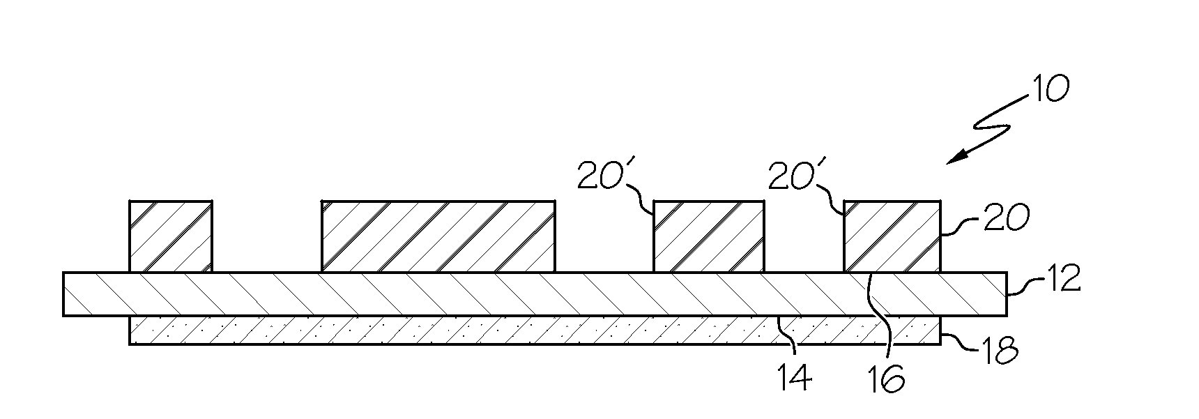
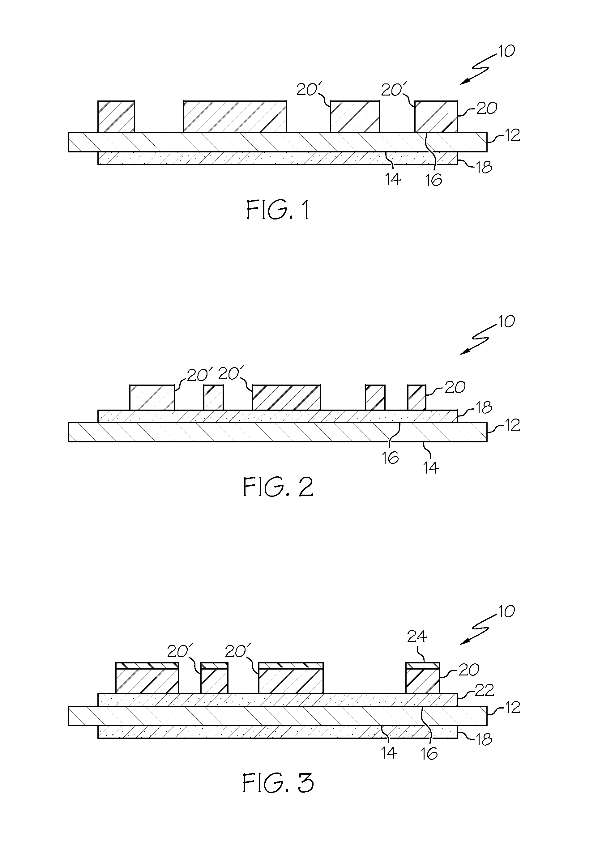
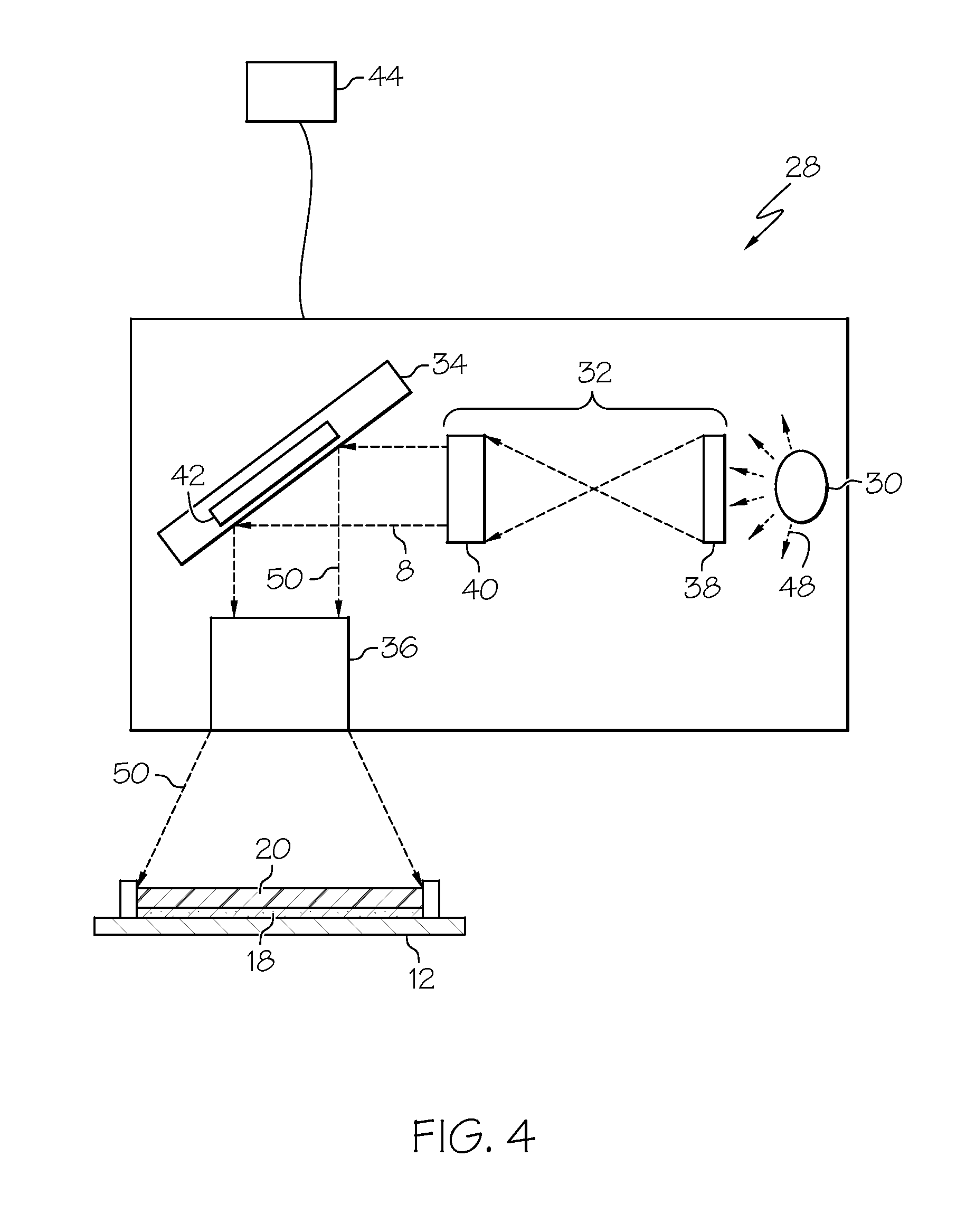
[0017]Embodiments of the present invention also provide methods of making a printing plate assembly for use in flexographic printing which, in one embodiment, comprises providing a cushion layer; applying a carrier layer on the cushion layer; applying at least one photopolymer layer on the carrier layer to form an integral printing plate assembly; is exposing portions of the photopolymer layer to a source of radiation to cure the photopolymer and form a relief image; and removing unexposed portions of the photopolymer layer. Preferably, the radiation source is a digital light imaging system. The method eliminates the need for a back exposure step to establish a floor.
[0023]With the assembly and digital imaging method of the present invention, the dimensions of each of the cushion layer(s), carrier layer, and photopolymer layer(s) are precisely controlled, which allows the relief depth of the desired image on the plate to be optimized for the desired end use. Further, the integral assembly eliminates the need for a “back exposure” step because the unit functions as a replacement for the “floor” formed by the back exposure step used in prior art methods. That is, the raised image formed by a single front exposure step of the final product performs like a raised image on a traditional photopolymer floor formed from a back exposed method. The relief depth (i.e., the distance between the upper surface of the raised image in the photopolymer layer and the integrated carrier / cushion layer construction) which is achieved with the printing plate assembly of the present invention can be varied, as desired, from about 0.50 mm to about 2.00 mm by controlling the thickness of the applied photopolymer layer.

Problems solved by technology

However, such an assembly process is time consuming and subject to stacking tolerance problems due to tolerance variations in each individual is layer in the assembly.

Method used


Image

  • Flexographic printing plate assembly
  • Flexographic printing plate assembly
  • Flexographic printing plate assembly

Examples


Embodiment Construction

[0031]The practice of embodiments of the present invention provides several advantages over prior art methods and products which utilize a separate printing plate, cushion layer, and carrier layer, all of which must be assembled prior to use. By supplying a printing plate assembly including integral carrier, cushion, and photopolymer layers, an end user does not have to assemble the separate components prior to use, resulting in lower labor costs. In addition, the relief image depth may be more precisely controlled because the integral unit does not require a prior art back-exposure step, which has resulted in variations in floor thickness. Rather, the integral assembly and method of the present invention provides the formation of a relief image depth in the photopolymer layer of the integrated assembly in one step. The dimensions and layer thicknesses of the carrier, cushion and photopolymers can be precisely controlled and result in a final product which is ready for printing.

[003...


PUM


Abstract

A printing plate assembly for use in flexographic printing application is provided which includes an integral carrier layer, one or more cushion layers, and one or more photopolymer layers. The photopolymer layer(s) in the integral assembly are provided with relief images using digital imaging photopolymerization, which eliminates the need for a back exposure step and provides a precise relief depth for the plate.

Description

CROSS REFERENCE TO RELATED APPLICATIONS[0001]This application claims the benefit of U.S. Provisional Application No. 60 / 781,979 entitled PRINTING PLATE ASSEMBLY FOR FLEXOGRAPHIC PRINTING INCLUDING INTEGRAL CARRIER LAYER, CUSHION LAYER, AND PHOTOPOLYMER IMAGE TRANSFER ELEMENT filed Mar. 14, 2006. The entire contents of said application are hereby incorporated by reference.BACKGROUND OF THE INVENTION[0002]The present invention relates to a printing plate assembly for use in flexographic printing applications, and more particularly, to an improved printing plate assembly including an integral carrier layer, cushion layer, and a photopolymer layer, which assembly provides a precise relief depth. The assembly is easily mounted on a flexographic cylinder and printed by an end user.[0003]Flexographic printing is a form of relief printing which utilizes relief printing plates wrapped around a printing cylinder to transfer ink onto a substrate. Flexographic printing is primarily used in high...

Claims


Application Information

Patent Timeline
IPC IPC(8): G03F7/00
CPCB41N1/12G03F7/11G03F7/092
Inventor MCLEAN, MICHAEL E.GOSS, WILLIAM KREBS
Owner XSYS NORTH AMERICA CORP
Learn More