
Optical Imaging Balloon Catheters

Inactive Publication Date: 2007-09-20
PRESCIENT MEDICAL
View PDF43 Cites 26 Cited by
  • Summary
  • Abstract
  • Description
  • Claims
  • Application Information

AI Technical Summary

Problems solved by technology

Although vulnerable plaques are non-stenotic or nominally stenotic, it is believed that their rupture, resulting in the release of thrombotic contents, accounts for a significant fraction of adverse cardiac events.

Method used


Image

  • Optical Imaging Balloon Catheters
  • Optical Imaging Balloon Catheters
  • Optical Imaging Balloon Catheters

Examples


Embodiment Construction

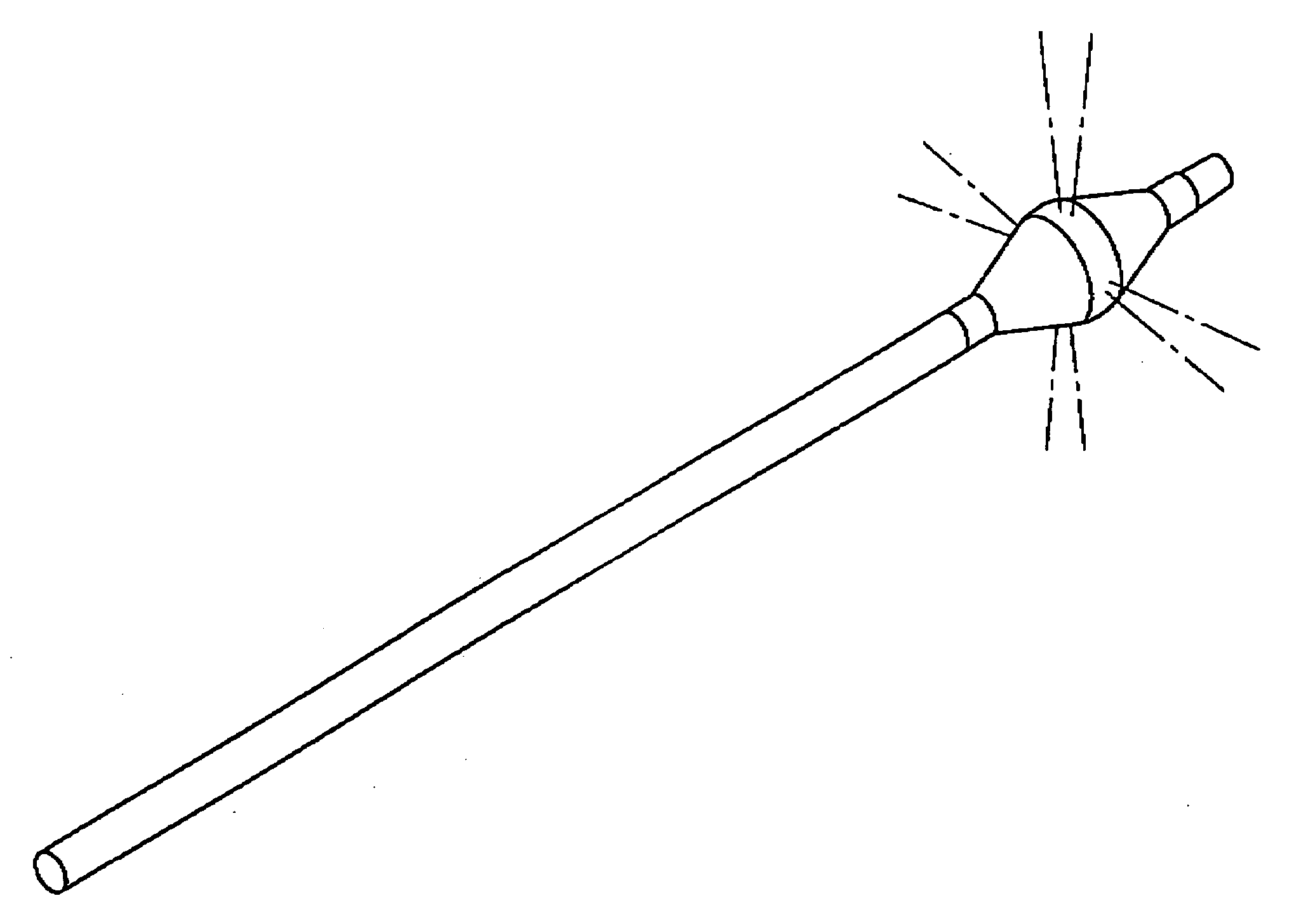
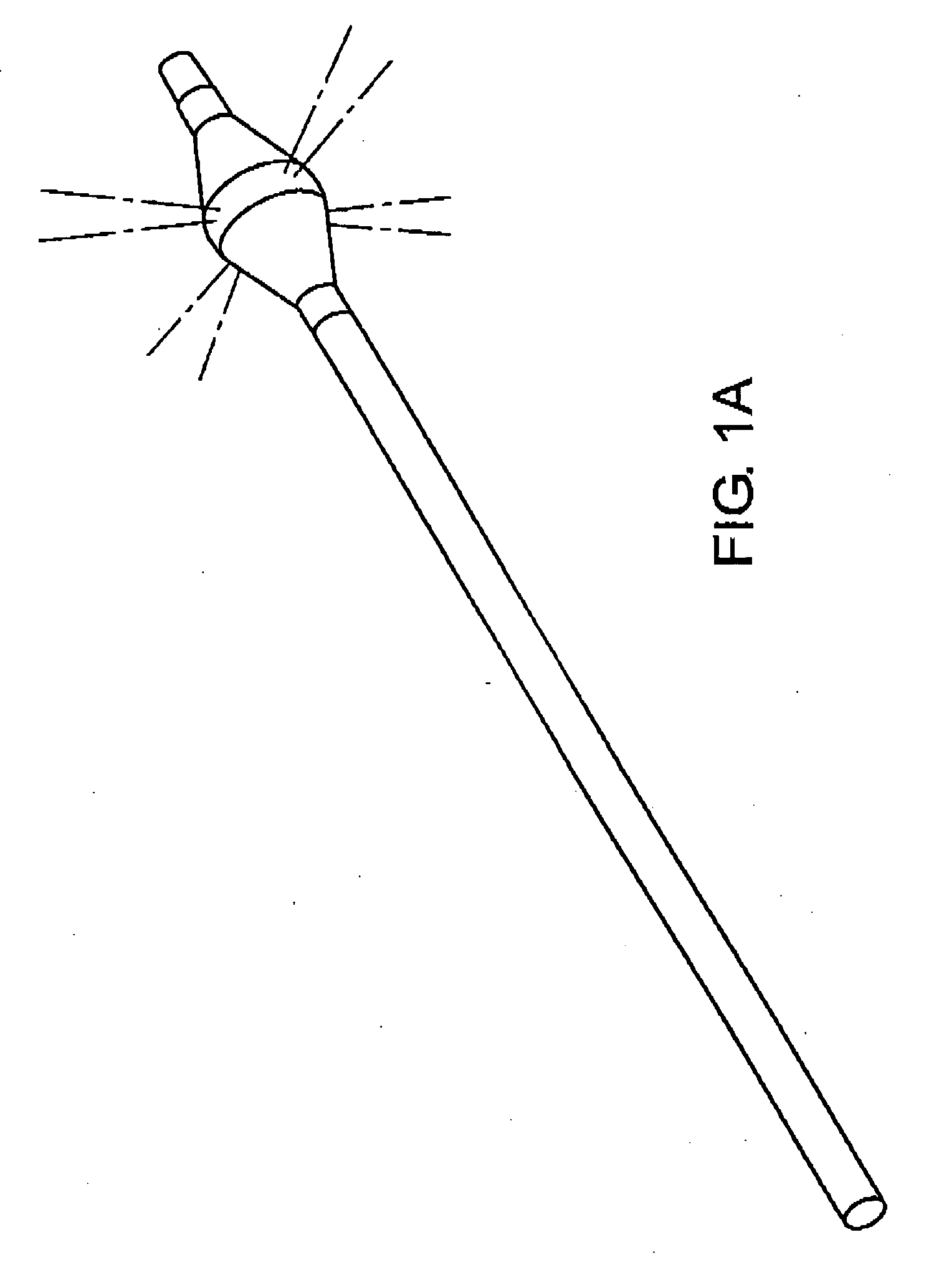
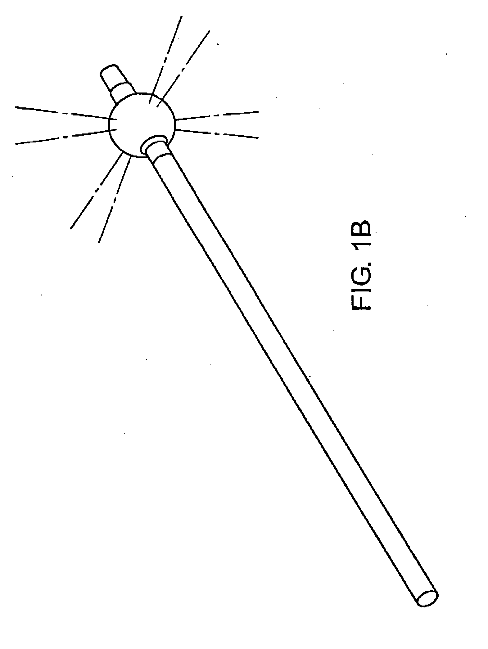
[0021] The present invention provides balloon catheters in which optical components for interrogating the walls of blood vessel lumens are disposed within the lumen of one or more inflatable balloon(s).

[0022] One embodiment of the invention provides an optical catheter for optically interrogating blood vessel walls that includes: an elongate catheter body having a distal end and a proximal end; a balloon section of the catheter comprising: a low-pressure inflatable balloon outwardly and radially disposed on the catheter, wherein the lumen of the balloon is in fluid communication with the proximal end of the catheter to permit inflation and deflation of the balloon; side-viewing optics disposed within the balloon section such that light can be emitted laterally through the balloon toward a vessel wall and light, such as light from the vessel wall, can be received for analysis.

[0023] Any suitable sort of side / lateral-viewing optical assembly(ies) may be used and numerous sorts of si...


PUM


Abstract

The present invention provides balloon catheters in which lateral-viewing optical components for interrogating the walls of blood vessel lumens are disposed within the lumen of the balloon(s). Advantageously, low pressure compliant balloons are used to minimize the possibility of injury to the blood vessels. The expanded balloons at least substantially clear blood from the optical path between the vessel wall that is interrogated and the lateral-viewing optics.

Description

[0001] This application claims the benefit of U.S. provisional patent application Ser. No. 60 / 778,393 filed Mar. 3, 2006, which is incorporated by reference herein in its entirety.FIELD OF THE INVENTION [0002] The invention relates generally to the field of vascular catheters having optical diagnostic capabilities. BACKGROUND OF INVENTION [0003] Various optical modalities for diagnostically interrogating blood vessel walls to locate and characterize atherosclerotic lesions have been proposed. What is needed are improved catheter probes, particularly for the location and diagnosis of vulnerable plaque lesions. Vulnerable plaques, which are sometimes known as high-risk atherosclerotic plaques, include arterial atherosclerotic lesions characterized by a subluminal thrombotic lipid-rich pool of materials contained and / or overlaid by a thin fibrous cap. Although vulnerable plaques are non-stenotic or nominally stenotic, it is believed that their rupture, resulting in the release of throm...

Claims


Application Information

Patent Timeline
IPC IPC(8): A61B6/00A61B5/05A61M29/00A61F2/958
CPCA61B1/00082A61B1/00165A61B1/00177A61B1/00179A61B1/3137A61B5/0066A61M2025/1086A61B5/0075A61B5/0084A61B5/0086A61B5/02007A61M25/1002A61B5/0071
Inventor KULA, JOHNGREEN, NICHOLAS
Owner PRESCIENT MEDICAL
Learn More