

Method and apparatus for controlling power supply in a computer system
a computer system and power supply technology, applied in the direction of power supply for data processing, instruments, computing, etc., can solve the problems of data loss between cpu and cache memory, recovery time, and the lik
- Summary
- Abstract
- Description
- Claims
- Application Information
AI Technical Summary
Benefits of technology
Problems solved by technology
Method used
Image

Examples
Embodiment Construction
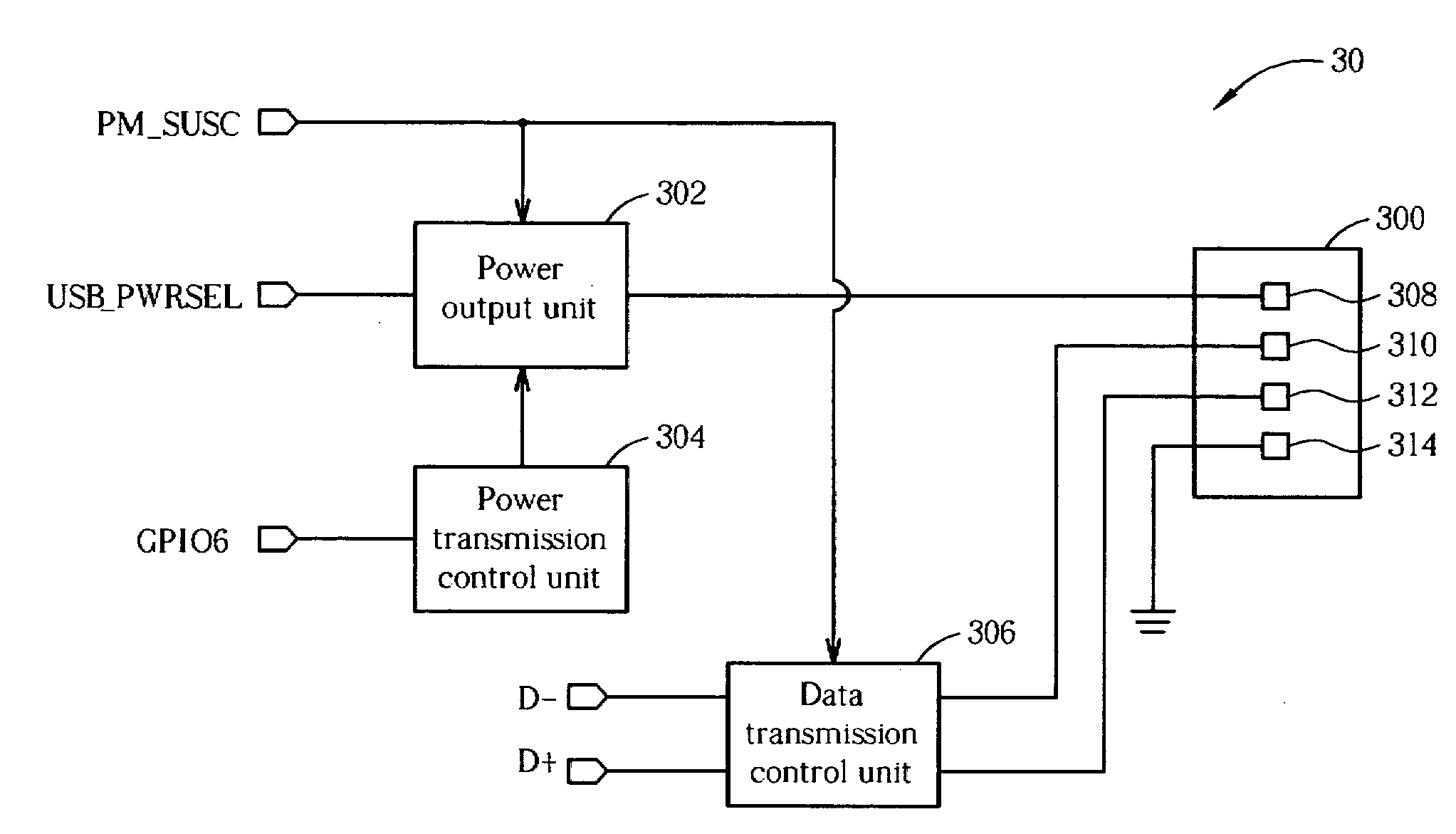
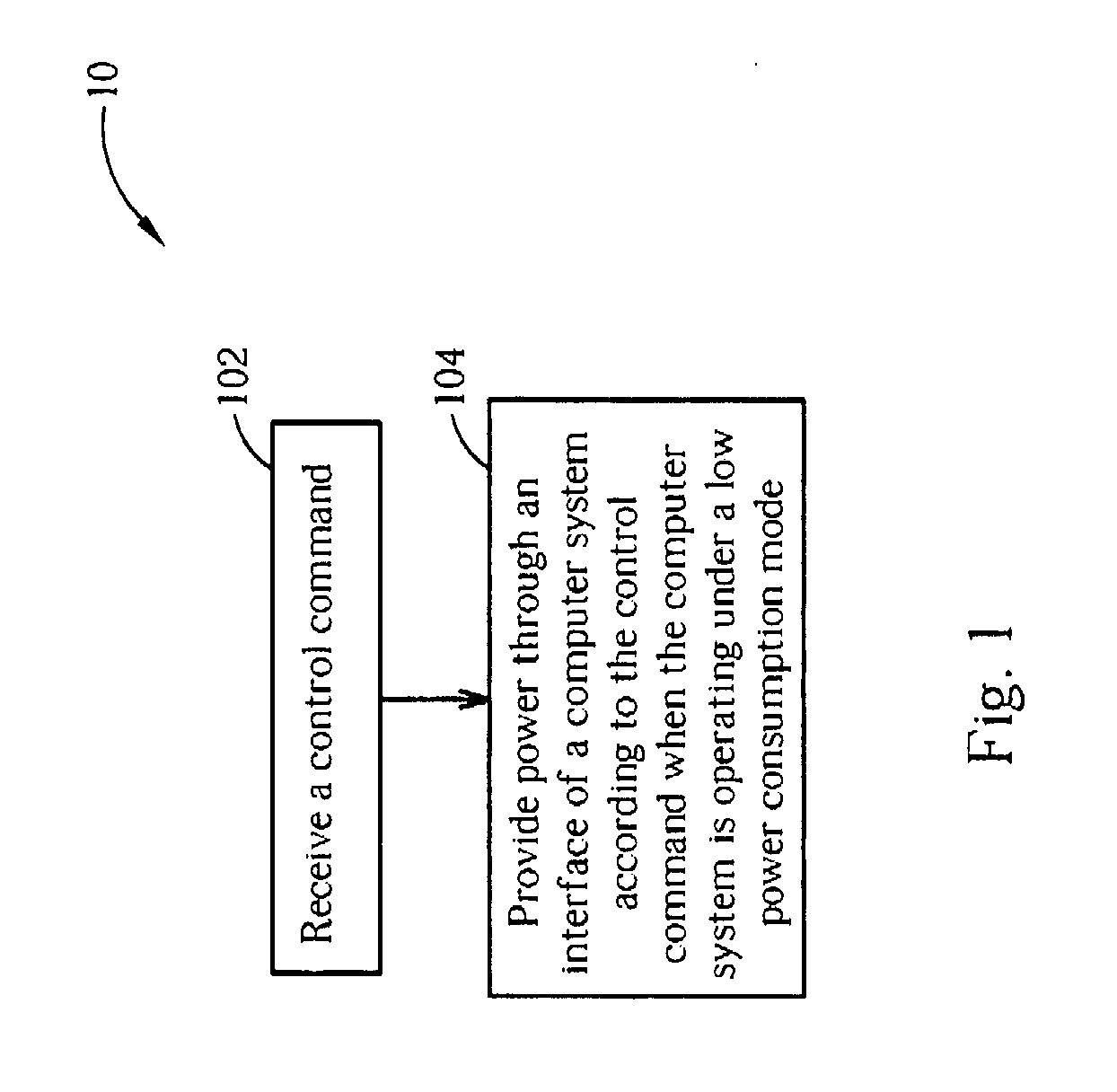
[0016]Please refer to FIG. 1. FIG. 1 is a diagram illustrating a power supply control workflow 10 of a computer system according to an embodiment of the present invention. As shown in FIG. 1, the workflow 10 includes the following steps:[0017]Step 102: Receive a control command.[0018]Step 104: Provide power through an interface of the computer system according to the control command when the computer system is operating under a low power consumption mode.
[0019]The aforementioned low power consumption refers to a sleep mode or a power off mode, such as the S3, S4, or S5 mode defined by the Advanced Configuration & Power Interface standard described previously. The computer system is preferably a portable computer system. When the computer system is operating under a sleep mode or a power off mode, very little electrical power or even no power is expended. Hence, under this condition, the embodiment of the present invention is able to provide power through an interface of the computer...
PUM
 Abstract
Description
Claims
Application Information