Body-insertable device system and in-vivo observation method

a body-insertable device and in-vivo observation technology, applied in the field of body-insertable device system and in-vivo observation method, can solve the problems of difficult to take an entire image of a desired observed region in the subject, difficult to move actively, and the position or direction of the imaging field in the body cavity cannot be changed actively

Active Publication Date: 2007-09-27
OLYMPUS CORP
View PDF9 Cites 184 Cited by
  • Summary
  • Abstract
  • Description
  • Claims
  • Application Information

AI Technical Summary

Problems solved by technology

However, the above described conventional body-insertable device is moved in the subject by the flow of the liquid filling the body cavity so that it is often difficult to move actively without relying on the flow of the fluid and the position or direction of imaging field in the body cavity cannot be changed actively.
Thus, it is often difficult to take an entire image of a desired

Method used


Image

  • Body-insertable device system and in-vivo observation method
  • Body-insertable device system and in-vivo observation method
  • Body-insertable device system and in-vivo observation method

Examples


first embodiment

Modification of First Embodiment

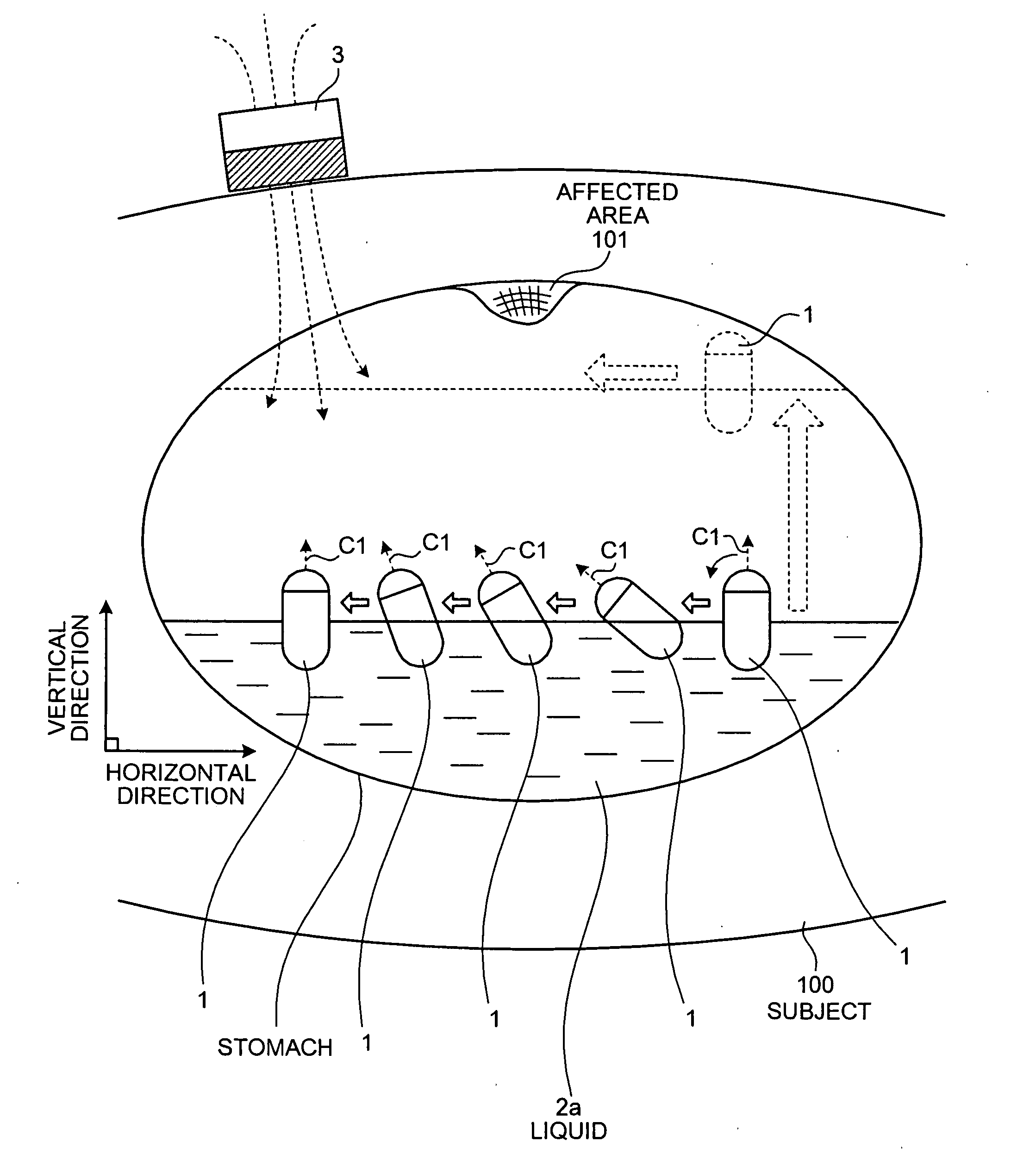
[0177] Next, a modification of the first embodiment of the present invention will be described. The above described first embodiment employs the capsule endoscope 1 that floats at the surface of the liquid 2a in the digestive canal introduced in the subject 100 and directs an imaging field above the surface of the liquid 2a in a vertical direction. However, a body-insertable device system according to the modification of the first embodiment includes a capsule endoscope that floats in the surface of the liquid 2a and directs an imaging field under the surface of the liquid 2a in a vertical condition, in place of the capsule endoscope 1.

[0178]FIG. 12 is a schematic view showing a configuration example of the body-insertable device according to the modification of the first embodiment of the present invention. As shown in FIG. 12, a capsule endoscope 21, as an example of the body-insertable device, includes a casing 20, in place of the casing 10 of the...

second embodiment

[0186] Next, a second embodiment of the present invention will be described. The above described first embodiment employs a capsule endoscope 1 having specific gravity equal to or smaller than the that of the liquid 2a introduced into a digestive canal of the subject 100; however a body-insertable device system according to the second embodiment employs a capsule endoscope having specific gravity greater than that of the liquid 2a, in place of the capsule endoscope 1.

[0187]FIG. 14 is a schematic view showing a configuration example of a body-insertable device system according to the second embodiment of the present invention. As shown in FIG. 14, the body-insertable device system of the second embodiment includes a capsule endoscope 31, in place of the capsule endoscope 1 of the body-insertable device system according to the first embodiment. Other elements are the same as those in the first embodiments and the same elements are represented by the same reference numbers.

[0188] The...

third embodiment

[0204] Next, a third embodiment of the present invention will be described. The above first embodiment employs the permanent magnet 3 for controlling the capsule endoscope 1 by its magnetic force. However, a body-insertable device system of the third embodiment employs an electrical magnet, in place of the permanent magnet 3.

[0205]FIG. 18 is a schematic view showing a configuration example of the body-insertable device system according to the third embodiment of the present invention. The body-insertable device system in the third embodiment includes a magnetic field generator 43, in place of the permanent magnet 3 of the body-insertable device system in the first embodiment, and a workstation 40, in place of the workstation 4. Other elements are the same as those of the first embodiment and the same elements are represented by the same reference numbers.

[0206] The magnetic field generator 43 includes a magnetic field generator 43a for generating a magnetic field toward the capsul...


PUM


Abstract

An object of the present invention is to actively control at least one of the position and direction of the imaging field in a subject and to observe a desired observed region in the subject certainly in a short period of time. A body-insertable device system according to the present invention includes a capsule endoscope 1 introduced into a subject and a permanent magnet 3. An imaging unit of the capsule endoscope 1 for taking an image inside the subject is fixed in a casing. The capsule endoscope 1 includes a drive unit for changing at least one of the position and posture of the casing in the liquid 2a which is also introduced in the subject 100. The permanent magnet 3 controls the operation of the drive unit for changing at least one of the position and posture of the casing in the liquid 2a.

Description

CROSS-REFERENCE TO RELATED APPLICATIONS [0001] This application is based upon and claims the benefit of priority from Japanese Patent Application No. 2005-380454, filed Dec. 28, 2005, the entire contents of which are incorporated herein by reference. BACKGROUND OF THE INVENTION [0002] 1. Field of the Invention [0003] The present invention relates to a body-insertable device system and an in-vivo observation method using a body-insertable device for being introduced into a subject and sequentially taking images in the subject. [0004] 2. Description of the Related Art [0005] Recently, in a field of endoscopes, a capsule-shaped body-insertable device (for example, a capsule endoscope) including an imaging function and a radio communication function has been proposed and a body-insertable device system for obtaining an image in a subject using this capsule endoscope has been developed. In order to observe (inspect) inside a subject, a capsule endoscope is swallowed through, for example,...

Claims


Application Information

Patent Timeline
IPC IPC(8): A61B19/00A61B1/06
CPCA61B1/00016A61B1/00036A61B1/00147A61B1/00156A61B1/00158A61B1/045A61B1/273A61B5/062A61B5/073A61B2019/2253A61B1/041A61B34/73A61B1/00
Inventor KAWANO, HIRONAOTAKIZAWA, HIRONOBUSEGAWA, HIDETAKEAOKI, ISAOHIRAKAWA, KATSUMIKOBAYASHI, SATOMIITO, HIDEO
Owner OLYMPUS CORP
Why Eureka
Try Eureka