Squeezing detection control method for consumable electrode arc welding

Active Publication Date: 2007-09-27
DAIHEN CORP
View PDF4 Cites 16 Cited by
  • Summary
  • Abstract
  • Description
  • Claims
  • Application Information

AI Technical Summary

Benefits of technology

[0029]It is therefore an object of the present invention to provide a squeezing detection control m

Problems solved by technology

Otherwise, erroneous detection may result due to the fact that the welding voltage Vw and the welding current Iw tend to greatly vary along with the change of the arc length which is caused by the change of the arc load during the arc period Ta.
Such filtering may cause a delay of a few tens of microseconds in the short/arc detection.
However, in middle-current through large-current operation such as welding in which short-circuit transfer welding and globular transfer welding are both present, or in globular transfer welding, or in spray transfer welding, the delay time Td often affects the welding stability since short-circuiting often occurs irregularly and therefore there is a wide range of variation in the droplet size when the sho

Method used


Image

  • Squeezing detection control method for consumable electrode arc welding
  • Squeezing detection control method for consumable electrode arc welding
  • Squeezing detection control method for consumable electrode arc welding

Examples


embodiment 1

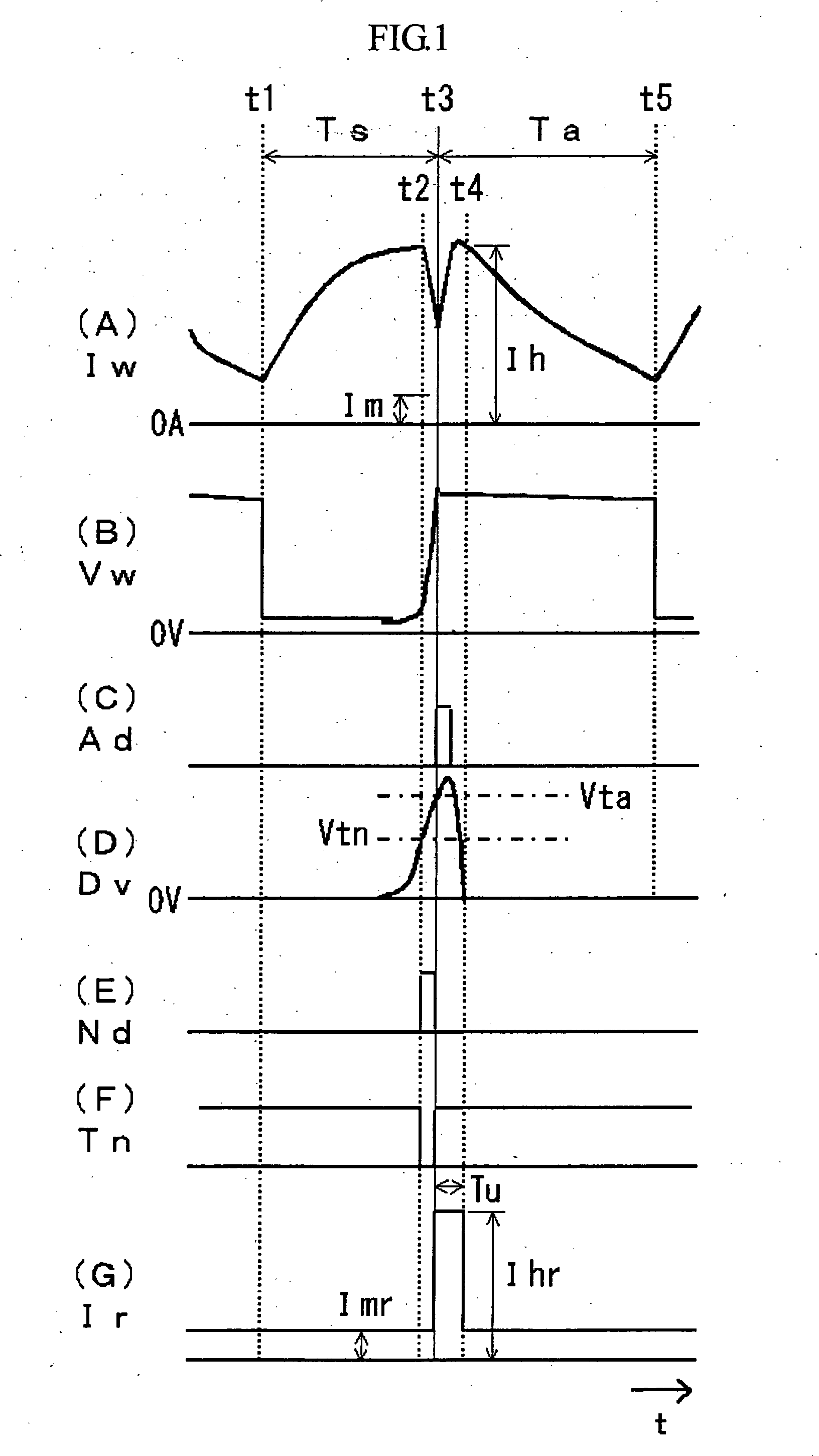
[0044]FIG. 1 is a timing chart depicting a squeezing detection control method in consumable electrode arc welding according to a first embodiment or Embodiment 1 of the present invention. Graph 1(A) shows the waveform of a welding current Iw, Graph 1(B) the waveform of a welding voltage Vw, Graph 1(C) the waveform of an arc recurrence determination signal Ad, Graph 1(D) the waveform of a voltage differentiation signal Dv, Graph 1(E) the waveform of a squeeze detection signal Nd, Graph 1(F) the waveform of a squeeze detection period signal Tn, and Graph 1(G) the waveform of an electric-current setting signal Ir. FIG. 1 corresponds to FIG. 8 described above. It should be noted that the short circuit determination signal Sd in Graph 8(C) is replaced by the arc recurrence determination signal Ad in Graph 1(C). Like FIG. 8, FIG. 1 shows a case in which the arc restrikes immediately after a squeezed droplet is detected. Hereinafter, reference will be made to FIG. 1.

[0045]When a squeezed d...

embodiment 2

[0050]FIG. 3 shows a timing chart depicting a squeezing detection control method in consumable electrode arc welding according to a second embodiment or Embodiment 2 of the present invention. Graphs 3(A)-3(G) show different patterns of the signals in FIG. 1 described above. FIG. 3 shows a case in which the squeeze period (i.e. the period from squeeze detection to arc recurrence) is relatively short. In general, the squeeze period can be divided into two categories: normal length squeeze period and relatively short length squeeze period. The normal length of the squeeze period may be a few hundreds of microseconds, whereas the relatively short length may be no greater than 100 μs, which is the case with Embodiment 2. If middle-to-high current range welding has a relatively short squeeze period, it may be better to maintain the welding current Iw at the present level rather than to decrease it rapidly for the purpose of ensuring stable welding.

[0051]Specifically, when a squeezed dropl...


PUM

PropertyMeasurementUnit
Electrical resistanceaaaaaaaaaa
Electric potential / voltageaaaaaaaaaa

Abstract

A squeezing detection control method is provided for consumable electrode arc welding in which a cycle of arc generation and short-circuiting is repeated between a consumable electrode and a base metal. First, squeezed droplet is detected as a premonitory sign of arc recurrence at the end of the short-circuiting. This detection is based on a fact that a squeeze detection reference value is attained by a differential value of the voltage or resistance between the consumable electrode and the base metal. Then, a welding current supplied to a short-circuit load is rapidly decreased upon detection of the squeezed droplet. Upon recurrence of the arc, the welding current is increased. This arc recurrence is detected by a fact that the differential value attains an arc recurrence reference value which is greater than the squeeze detection reference value.

Description

BACKGROUND OF THE INVENTION[0001]1. Field of the Invention[0002]The present invention relates to a squeezing detection control method in consumable electrode arc welding for reducing spattering of molten metal by rapidly decreasing a welding current, immediately before the arc restrikes, upon detection of the squeeze of the droplet during the short circuit period.[0003]2. Description of the Related Art[0004]FIG. 5 shows electric-current and voltage waveforms and a droplet in consumable electrode arc welding in which the cycle of a short circuit period Ts and an arc period Ta is repeated. Specifically, Graph 5(A) shows a welding current Iw which passes through the consumable electrode (hereinafter called welding wire 1). Graph 5(B) shows a welding voltage Vw applied between a power supply chip and a base metal 2. Pictures 5(C)-5(E) show how a droplet 1a changes in shape.[0005]During the short circuit period Ts between Time Point t1 and Time Point t3, a droplet 1a is at the tip of the...

Claims


Application Information

Patent Timeline
IPC IPC(8): B23K9/10
CPCB23K9/073B23K9/0956B23K9/0953B23K9/093
Inventor ERA, TETSUO
Owner DAIHEN CORP
Why Eureka
Try Eureka