Swinging Apparatus

a technology of swinging apparatus and swinging rod, which is applied in the direction of movable seats, transportation items, gearing, etc., can solve the problems of degrading the aesthetic aspect of the apparatus and increasing the size of the apparatus, and achieves the effects of simple structure, reduced apparatus size and smooth operation

Inactive Publication Date: 2007-09-27
TOYOTA SHATAI KK
View PDF7 Cites 20 Cited by
  • Summary
  • Abstract
  • Description
  • Claims
  • Application Information

AI Technical Summary

Benefits of technology

[0008] The swinging apparatus in accordance with the present invention is configured so that when a swing arm is in a set position, a mount and a base member are diagonally positioned. This prevents the swing arm from extending upward from the mount. Consequently, the size of the apparatus can be reduced across the height.
[0009] Further, according to another embodiment of the present invention, when the swing arm is swung, a movable sprocket rotatively moves in a direction opposite to a swinging direction. This allows the mount to be held in a horizontal posture with respect to the base member regardless of the swinging operation of the swing arm. Further, some such posture holding portions operate via a four-node link, that is, four supporting points. However, the sprocket operates via two supporting points, and thus has a simple structure and operates smoothly.
[0010] According to another embodiment of the present invention, when a driving portion rotatively moves a horizontal rotating shaft, the mount is swung (elevated or lowered and moved forward or backward) via the swing arm. As the horizontal rotating shaft rotates, its rotating operation is directionally converted into a rotating operation around a vertical rotating shaft, with the converted rotating operation transmitted to a rotatively moving portion. This rotatively moves the base member and thus the mount. Thus, both swinging operation and rotatively moving operation can be performed using the same driving source. This makes it possible to reduce the number of parts required and thus the size of the whole apparatus.
[0011] Moreover, according to another embodiment of the present invention, a converting portion comprises such a pair of gears as allows the rotating shafts to cross at right angles. The converting portion thus has a simple structure.
[0012] Furthermore, according to another embodiment of the present invention, a transmitting portion joins two sprockets together via a belt. Consequently, even if the two sprockets are spaced from each other, their power can be easily transmitted.
[0013] Further, according to another embodiment of the present invention, the swing arm is inverted, that is, rotatively moved through about 180° around the horizontal rotating shaft. This ensures a sufficient stroke for a seat portion when it swings to the exterior or interior of the vehicle (for a swinging angle of 180°, a stroke is ensured which is almost double the length of the swing arm).

Problems solved by technology

This increases the size of the apparatus even in a vertical direction, thus degrading the aesthetic aspect of the apparatus.

Method used


Image

  • Swinging Apparatus
  • Swinging Apparatus
  • Swinging Apparatus

Examples


embodiment 1

[0039] An embodiment of the present invention will be described with reference to FIGS. 1 to 16.

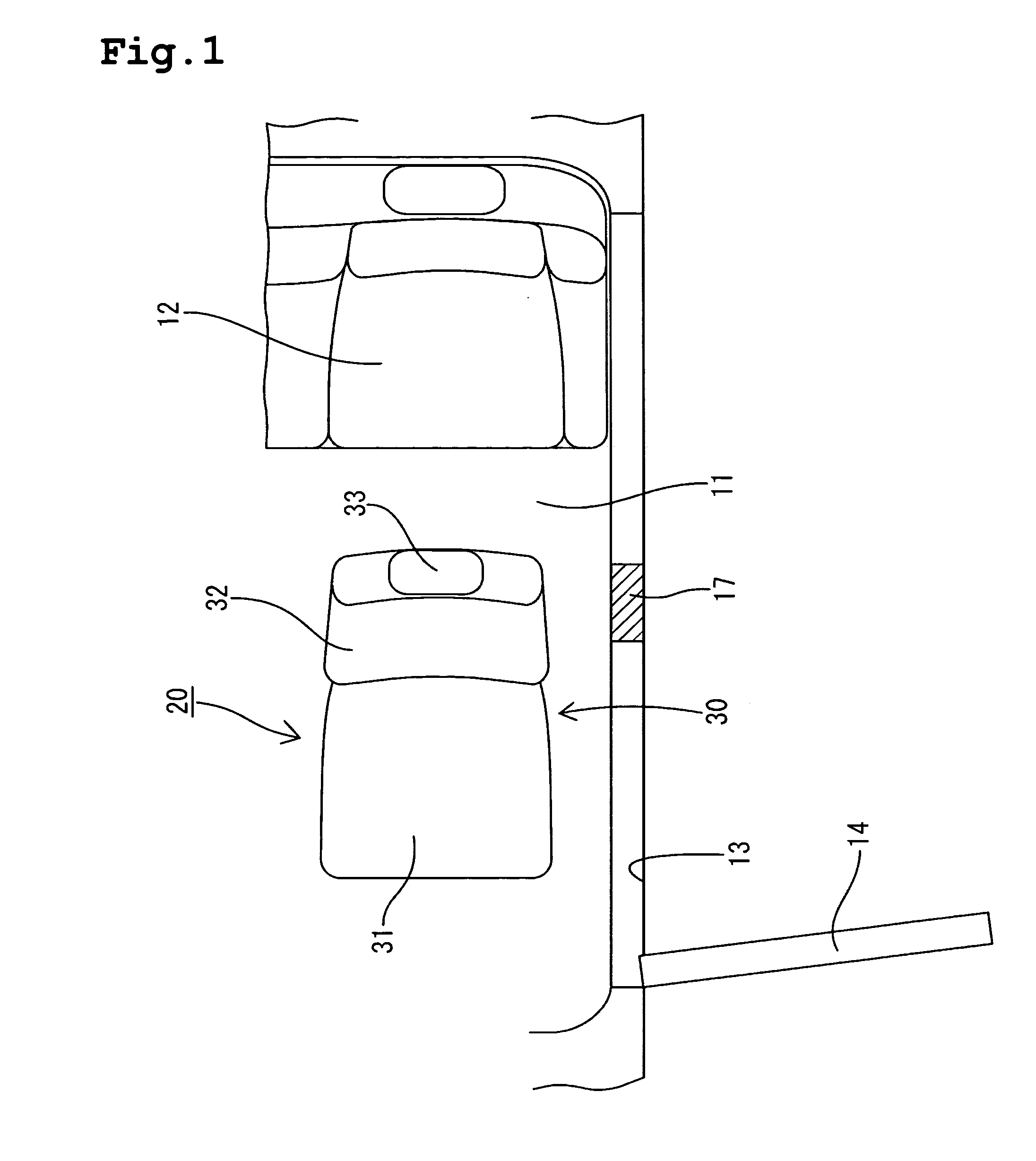
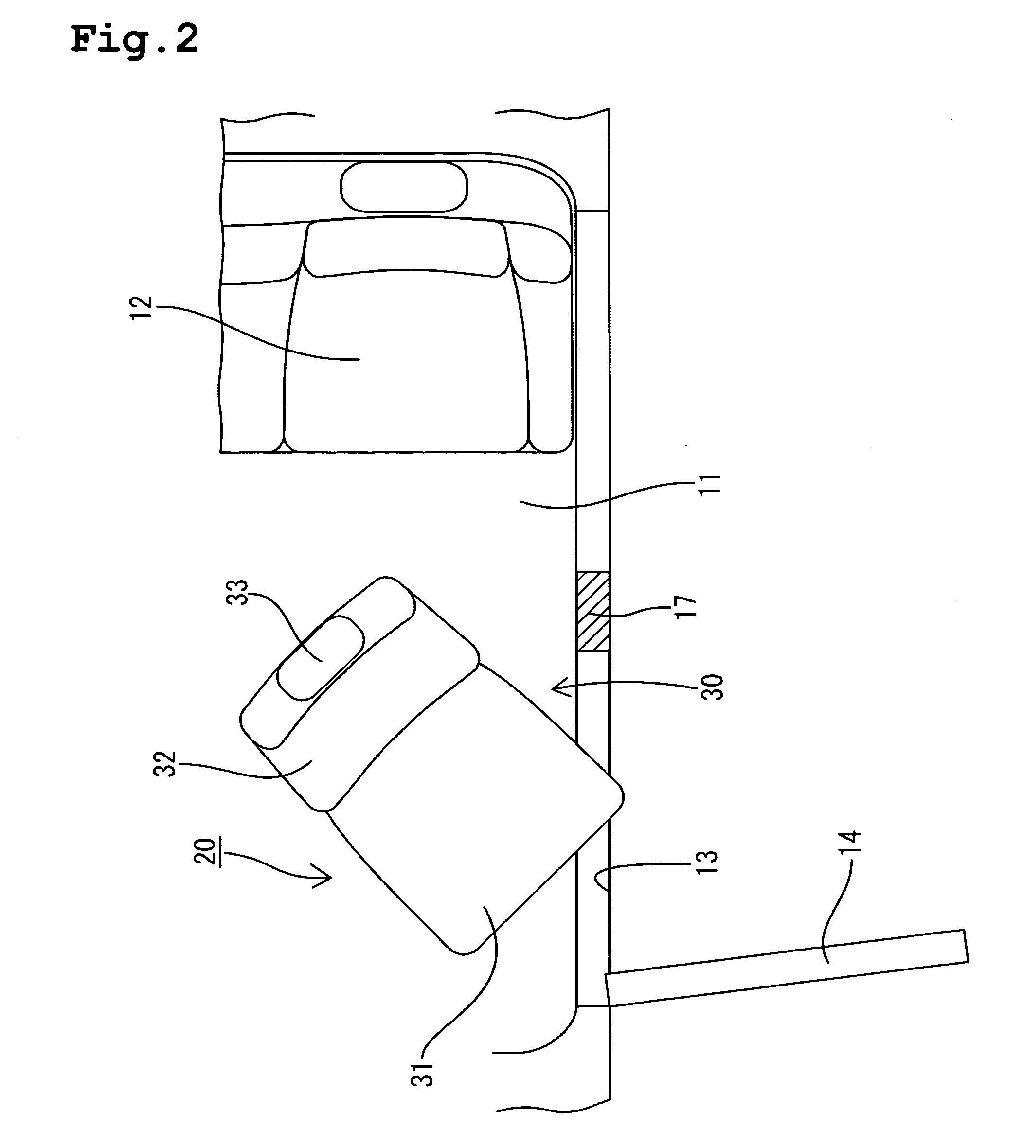
[0040]FIG. 1 shows half of a passenger seat in a car applied to the present embodiment. In a compartment, a passenger seat 20 and a rear seat 12 are arranged on a floor panel 11. A door opening 13 is provided on a side of the passenger seat 20. A door 14 is attached to the door opening 13 so that it can be opened and closed. A center pillar 17 is formed behind the door opening 13.

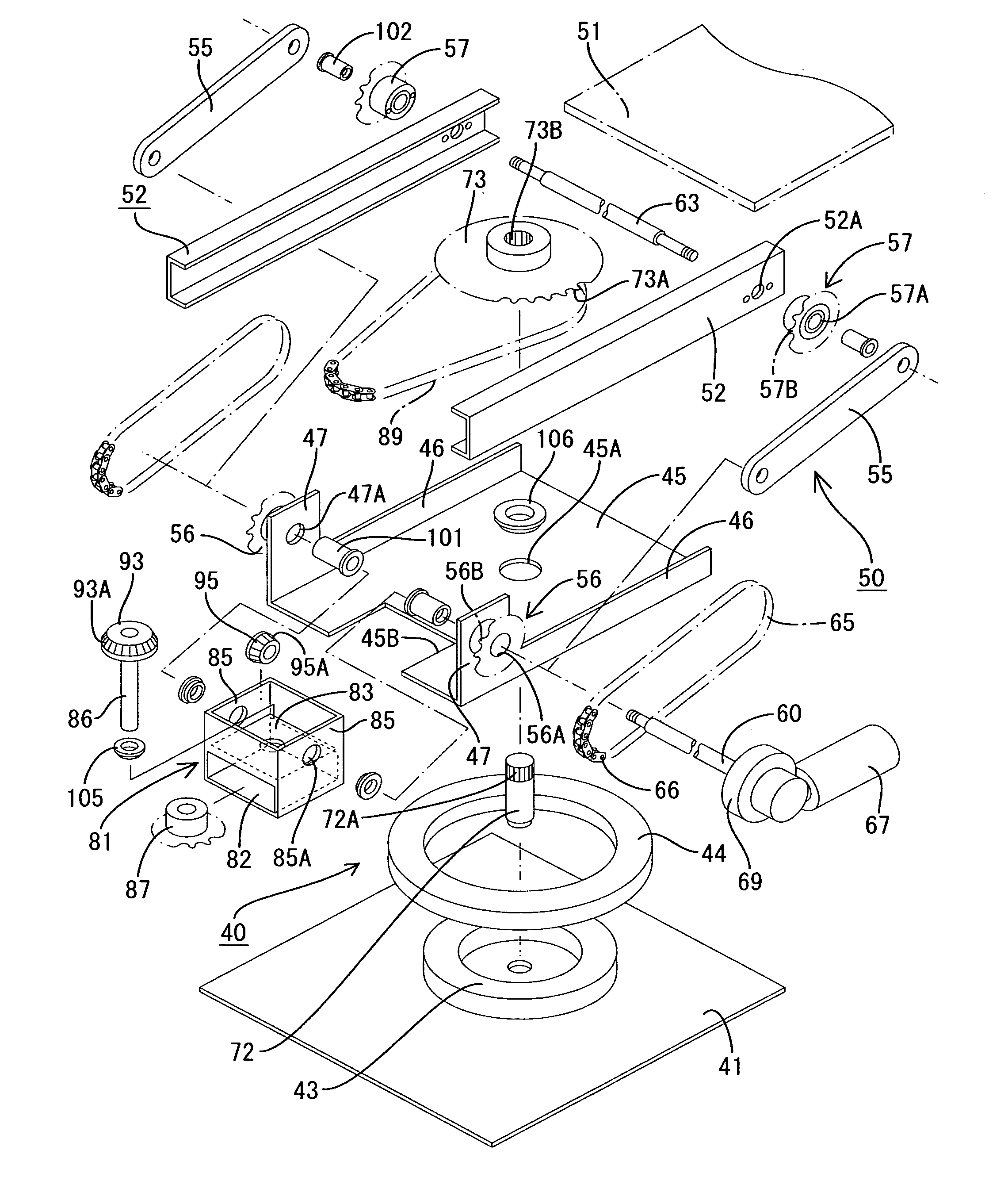
[0041] The passenger seat 20 is composed of a seat portion 30 consisting of a seat cushion 31, a seat back 32, and a headrest 33, and a rotatively moving and swinging apparatus M. The apparatus M causes the seat portion 30 to perform an internal slide operation for adjusting the seat position in the compartment and an external projecting operation and retracting operation for allowing a passenger to get in or out smoothly. The projecting and retracting operation causes the seat portion 30 to perform a combinati...


PUM


Abstract

In a swinging apparatus (rotatively moving and swinging apparatus), a swing arm 51 positions a rotatively moving pedestal 45 and a cushion base 51. The swing arm 51 is swung around a driving shaft 60 to swing the cushion base 51, that is, to elevate or lower the cushion base 51 and to move it forward or backward. The cushion base 51 supports a seat portion 30. When the seat is in a forward position in which it is directed toward the front of the vehicle, the swing arm 55 diagonally connects the members 51 and 45 together (Z type). This prevents, in the forward position, the swing arm 55 from extending upward from the cushion base 51 or the rotatively moving pedestal 45 from extending laterally from the seat portion 30. Therefore, the size of the apparatus can be reduced across the width and height.

Description

TECHNICAL FIELD [0001] The present invention relates to a swinging apparatus. BACKGROUND ART [0002] An elevating and lowering apparatus has been proposed which is installed in an uneven place or in a van type vehicle to perform a loading or unloading operation (for example, Patent Document 1). As shown in FIG. 17, the elevating and lowering apparatus is mainly composed of a pallet 1 on which a load can be placed, a base member 2 disposed on a side of the pallet 1, a driving motor 3 provided on the base member 2, and a swinging arm 5 that positions the base member 2 and a suspension arm 1A standing on the pallet 1. The swinging arm 5 can be swung around its connection portion 5A connected to the base member 2 to elevate and lower the load on the pallet 1. [0003] In this structure, the swinging arm 5 is connected to the suspension arm 1A of the pallet 1. Accordingly, even while out of use, the swinging arm 5 extends upward far from the pallet 1. This increases the size of the apparatu...

Claims


Application Information

Patent Timeline
Patent Type & Authority Applications(United States)
IPC IPC(8): A47C1/00B60N2/14B60N2/24B60P1/44F16H35/00F16H37/12
CPCB60N2/14B60N2/245F16H37/126F16H37/12B60P1/4428
Inventor TSUJIMOTO, HISASIYASUFUKU, SIGERUTSUZUKI, HIDEOYAMAUCHI, HIDENORI
Owner TOYOTA SHATAI KK
Why Eureka
Try Eureka