
Floor covering removal machine

Inactive Publication Date: 2007-09-27
MANNERS HERBERT C
View PDF20 Cites 18 Cited by
  • Summary
  • Abstract
  • Description
  • Claims
  • Application Information

AI Technical Summary

Benefits of technology

[0028] The removal machine may also further incorporate one or more or a plurality of side rollers that can be mounted to the drive frame in a number of locations, including about opposite extents of the feed side and or ejection side of the drive frame. Preferably, the side rollers rotate about a generally vertical axis and extend slightly outside the profile of the drive frame to prevent abrasion of the walls or the other appurtenances extending about the floor surface, and to guide the removal machine along a contour of a wall.

Problems solved by technology

Those skilled and knowledgeable in the related fields of technology have long understood that such high-traffic environments establish unfavorable wear conditions for carpeting and other types of floor coverings.
Many problems have resulted and include accelerated wear and deterioration.
This type of damage often may occur as a result of unwanted shifting of the floor covering during use due to the movement of individuals, furniture and equipment.
Despite improvement in the wear and damage that results from better fastening methods, floor coverings still see wear and unavoidable deterioration over time, which necessitates removal and replacement.
In some instances, the worn covering is covered over with a new floor covering, but such overlayments are only possible a limited number of times. The layered coverings create instability due to continued deterioration of the underlying and new covered materials, as well as the eventual disintegration of the adhesives typically applied in the interstices between the layers.
The capability to remove a floor covering that is secured to the sub-floor using newer fastening techniques has become more difficult with each advance in fastening technology.
In turn, the ever increasing difficulty has led to the need for more capable removal methods and technologies.
Another previous attempt is described in U.S. Pat. No. 4,948,451 to Foltz and is limited to an automatic carpet stripping apparatus that includes a self-propelled carpet machine with a frame mounted pair of motorized rollers that receive a loose end of a carpet and then pull the carpet up off of its supporting surface.
The various prior art devices and machines that purport to reduce the amount of manual labor needed to remove a floor covering, such as a carpet from the floor surface, fail to overcome a number of disadvantages that persist for users who are confronted with removing floor coverings.
In one respect, most prior art machines remain unwieldy and of such a large size that prevents their use in narrow hallways and other confined spaces.
Additionally, the larger profile machines can be expensive as a result of the many moving parts and complex components that are needed to manufacture and operate the assemblies.
Further, the more complex machines are more expensive to buy and maintain as a result of such complexity.
Other shortcomings that persist include an undesirable amount of noise and dust that results from the overly large size and complexity of many of such devices.
Even so, the devices offered by Ketterer and Johnson, while directed to reducing complexity and weight, have introduced other disadvantages such as less power and pulling forces.
These prior attempts describe different devices that each seek to improve the state of the art, however, in the field of removing floor coverings, such as carpeting and the like, many challenges remain despite the previous innovations.
The smaller machines that have been devised remain difficult and slow to use for removal of floor coverings that are very securely fastened to a floor surface.
Larger more powerful machines remain bulky, unwieldy and too large to maneuver into confined areas, and too heavy to enable easy transport to and from locations.
Such larger machines are also more complex and require more frequent servicing of the many moving parts.
Further, most of such larger machines create a substantial amount of dust during the removal operation, and remain too noisy for use in many residential, commercial, and industrial settings and applications.
As a result, the use of such larger machines is limited to off hours when increased dust and high volume sound will not interfere with other regular activities on the premises.
Additionally, many, if not all such machines, including those described above, inject new problems to the difficulties in the lifting and removing operations.
Mainly, the prior, more powerful machines most often operate at speeds and with forces that tend to rend the floor covering during removal, which occurs often and especially on start-up of the machine.
Such rending results in more dust and produces shredded material and debris that fouls the machines, which requires frequent stops and starts to clean and reset the machine.
Attempts to lessen the rending of the floor covering during removal have resulted in even more complex mechanisms or inadequate pulling and lifting capabilities.

Method used


Image

  • Floor covering removal machine
  • Floor covering removal machine
  • Floor covering removal machine

Examples


Embodiment Construction

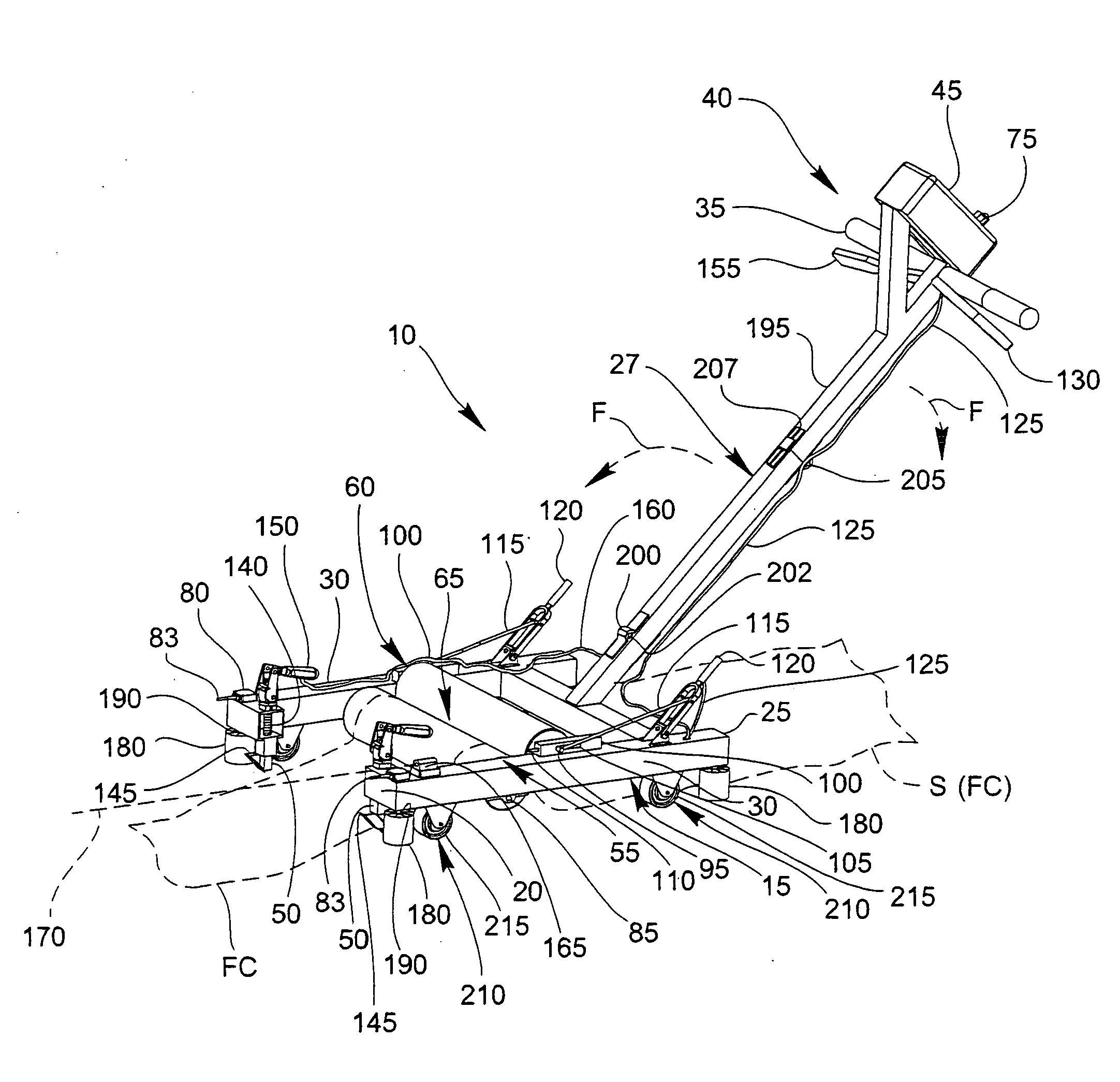
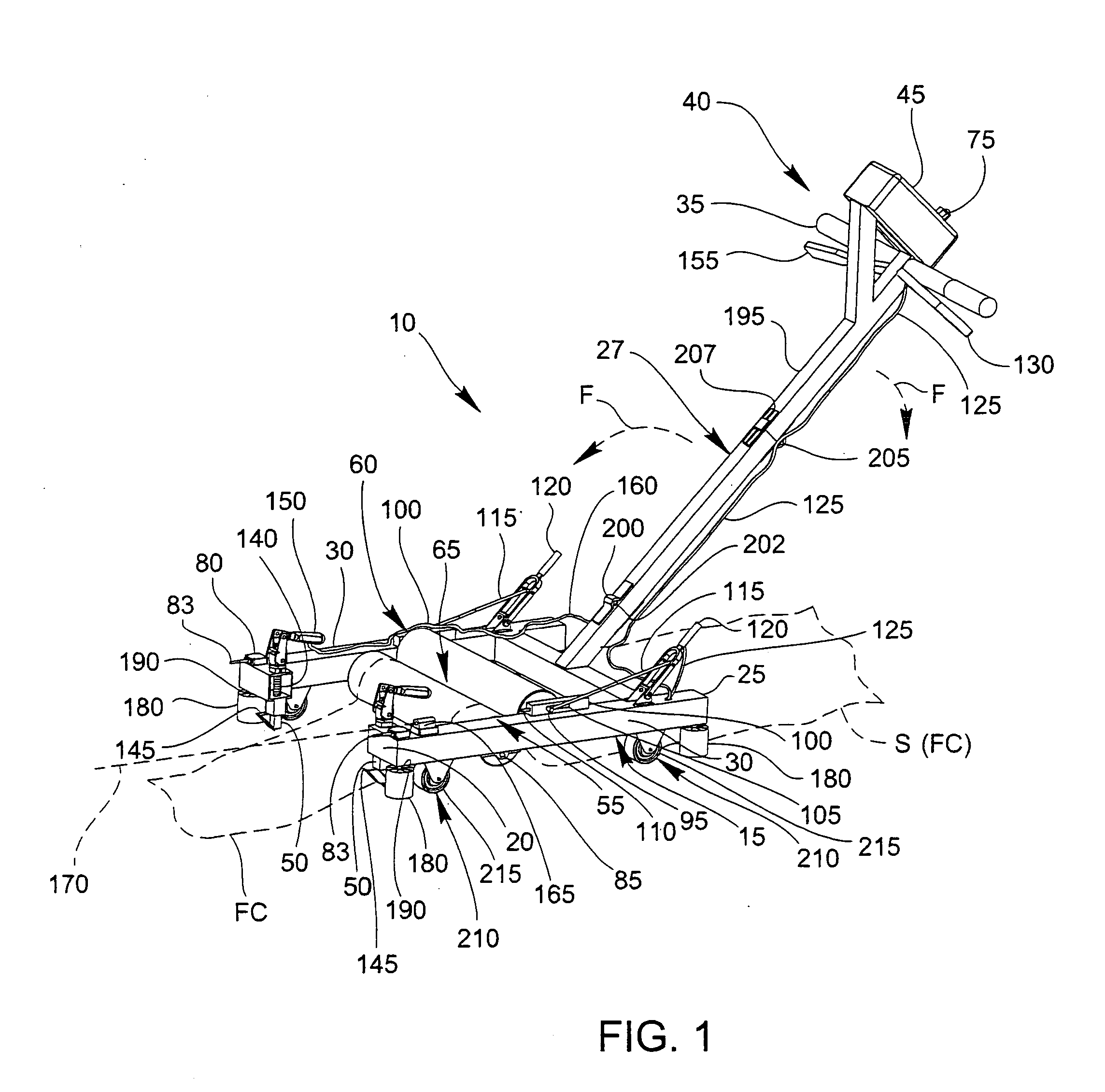
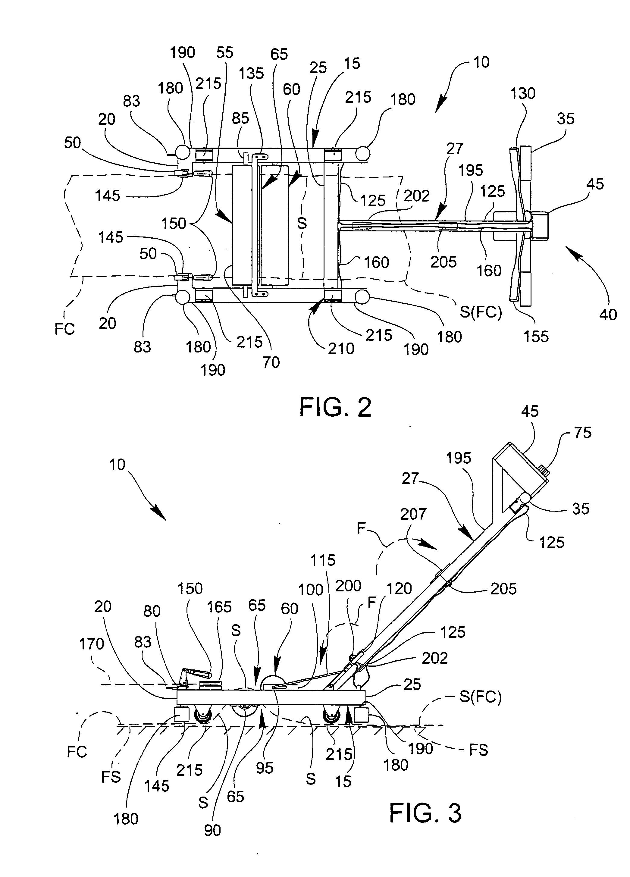
[0038] With reference now also to FIGS. 1 through 3, an embodiment of the inventive floor covering removal machine 10 is shown to include a drive frame 15 having a generally forward feed side 20, an opposite ejection side 25, and at least one cutter side 30. A folding extension 27 projects from the drive frame 15 and carries about a distal end a guide handle 35 positioned to maneuver the floor covering removal machine 10 during operation. Further, a control assembly 40 may also be included and may have a motor speed control 45 that together coact with the drive frame. As seen in FIGS. 1-3, the motor speed control 45 may be carried about the guide handle 35. The floor covering removal machine 10 preferably incorporates an optionally preferred at least one retractable floor covering cutter 50 that is deployable beneath the drive frame 15 and carried from the at least one cutter side 30.

[0039] The drive frame 15 also preferably includes at least one motorized drum 55 that is carried f...


PUM

PropertyMeasurementUnit
Speedaaaaaaaaaa

Abstract

A floor covering removal machine for removing a floor covering that is secured to a floor that includes a drive frame formed with an underside caster assembly, and feed, ejection, and oppositely arranged cutter sides. A variable speed, reversible, motorized drum is mounted about the frame and cooperates with a gripping idler roller that is releasably biased toward the drum to establish a grip interface which conveys the floor covering from the feed to the ejection sides. In operation, the floor covering is pulled through the grip interface and thereby removed from the floor. The machine also may include a collapsible guide handle extending from the drive frame and a motor speed control. Optional retractable floor covering cutters are included that are deployable in a floor contour-following configuration. An optional alignment laser pointer is mounted on the frame for alignment during operation.

Description

BACKGROUND OF THE INVENTION [0001] 1. Field of the Invention [0002] The invention advances that state of the art of removing floor coverings such as carpets that are glued or fastened to a floor surface. [0003] 2. Description of Related Art [0004] Floor coverings have been in use for the duration of recorded history. In more recent centuries, floor coverings have become more durable, and more suitable for use in residential and commercial high-traffic pedestrian areas. Those skilled and knowledgeable in the related fields of technology have long understood that such high-traffic environments establish unfavorable wear conditions for carpeting and other types of floor coverings. Many problems have resulted and include accelerated wear and deterioration. This type of damage often may occur as a result of unwanted shifting of the floor covering during use due to the movement of individuals, furniture and equipment. [0005] Attempts to reduce wear due to undesired shifting led to efforts...

Claims


Application Information

Patent Timeline
IPC IPC(8): E04B5/00E21C25/00
CPCE04G23/006Y10T156/1956Y10T156/1174
Inventor MANNERS, HERBERT C.
Owner MANNERS HERBERT C
Learn More