Automotive regenerative and friction braking system and control method

a technology of regenerative and friction braking and control method, which is applied in the direction of braking system, braking components, transportation and packaging, etc., can solve the problems of inability to use regenerative system, insufficient regenerative braking, and insufficient regenerative braking capability, etc., and achieve the effect of increasing the availability of braking

Inactive Publication Date: 2007-09-27
FORD GLOBAL TECH LLC
View PDF17 Cites 30 Cited by
  • Summary
  • Abstract
  • Description
  • Claims
  • Application Information

AI Technical Summary

Benefits of technology

[0011] It is an advantage of a method and system according to the present invention that regenerative braking may be maintained on a vehicle having both regenerative and friction braking capability, even if coordinated braking becomes inoperative or the brake system control module exhibits an indication of degraded friction braking performance capability.
[0012] It is a further advantage of a method and system according

Problems solved by technology

Regenerative braking is almost always combined with friction braking, because regenerative braking is usually not adequate for all situations, for a host of reasons.
A principle reason militating in favor of supplementing regenerative braking with friction braking exists because regenerative brakes are usually not available on all of the wheels of a vehicle.
A second reason limiting the capability of regenerative brakes deals with the need to store energy.
Thus, if a battery is fully charged, the regenerative system cannot be employed unless a resistance load bank is incorporated within the vehicle at added cost, weight, complexity and the

Method used


Image

  • Automotive regenerative and friction braking system and control method
  • Automotive regenerative and friction braking system and control method
  • Automotive regenerative and friction braking system and control method

Examples


Embodiment Construction

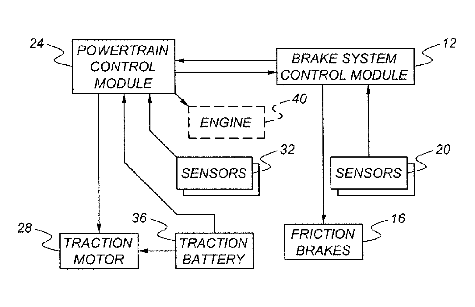
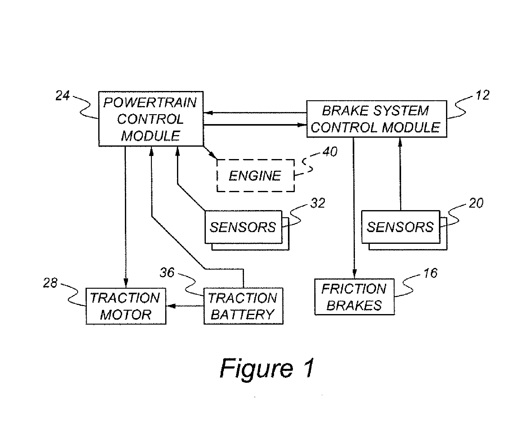
[0017] As shown in FIG. 1, an automotive regenerative and friction braking system includes a friction braking subsystem having a number of friction brakes, 16, which may be of the disk or drum type or yet other types of friction brakes known to those skilled in the art and suggested by this disclosure. The friction braking subsystem also includes a number of brake parameter sensors, 20, such as a brake pedal position sensor, or a brake system hydraulic pressure sensor, or a brake pedal pressure sensor, or a brake pedal movement sensor. All of sensors 20 and friction brakes 16 are operatively connected brake system control module 12, which performs a function of coordinating controlling the overall braking of the vehicle. Brake system control module 12 normally operates the friction and regenerative braking subsystems in a series configuration.

[0018] Brake system control module 12 communicates with powertrain control module 24, which is operatively connected with traction motor 28, ...


PUM


Abstract

An automotive regenerative and friction braking system uses a separate brake system control module and a powertrain control module. The brake system control module normally operates the friction and regenerative brakes in a coordinated, or series, configuration. In the event that the brake system control module becomes inoperative, the powertrain control module will operate the regenerative braking system in a parallel, or independent, configuration.

Description

BACKGROUND OF THE INVENTION [0001] The present invention relates to an automotive vehicle having both a friction braking subsystem and a regenerative braking subsystem, as well as at least one software-based controller for running the braking subsystems in a series configuration during normal operation, and in a parallel configuration in the event that a brake system controller becomes inoperative. [0002] Vehicles having either full or partial electrodrive capability, such as purely battery powered vehicles on the first hand, and hybrid gasoline-electric vehicles on the other hand, typically utilize regenerative braking as a principal means for enhancing vehicle fuel economy. Regenerative braking is almost always combined with friction braking, because regenerative braking is usually not adequate for all situations, for a host of reasons. [0003] A principle reason militating in favor of supplementing regenerative braking with friction braking exists because regenerative brakes are u...

Claims


Application Information

Patent Timeline
IPC IPC(8): B60T8/64
CPCB60L7/18B60T1/10B60T2270/604B60W10/06Y02T10/6286B60W10/184B60W20/00B60W30/18127B60W2540/12B60W10/08Y02T10/62B60W2510/18B60W10/18B60W20/13
Inventor CROMBEZ, DALESMITH, MATT
Owner FORD GLOBAL TECH LLC
Why Eureka
Try Eureka