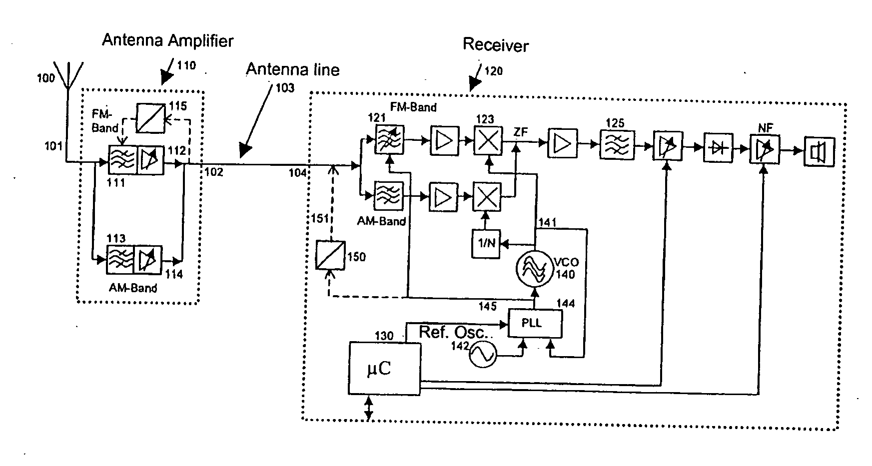
[0006] The information regarding which channel or frequency the desired receiving frequency is, is present in the receiving part. This information is now used to control a narrow-band filter in the antenna
amplifier in such a manner that the deterioration of the basic channel is largely prevented. The filter is situated in the signal path, in front of the active amplifier element of the antenna amplifier. In each instance, the
passband of the narrow-band filter is adjusted to the frequency of the desired basic channel. This reduces the
signal level of the unwanted frequencies and increases the received power of the entire
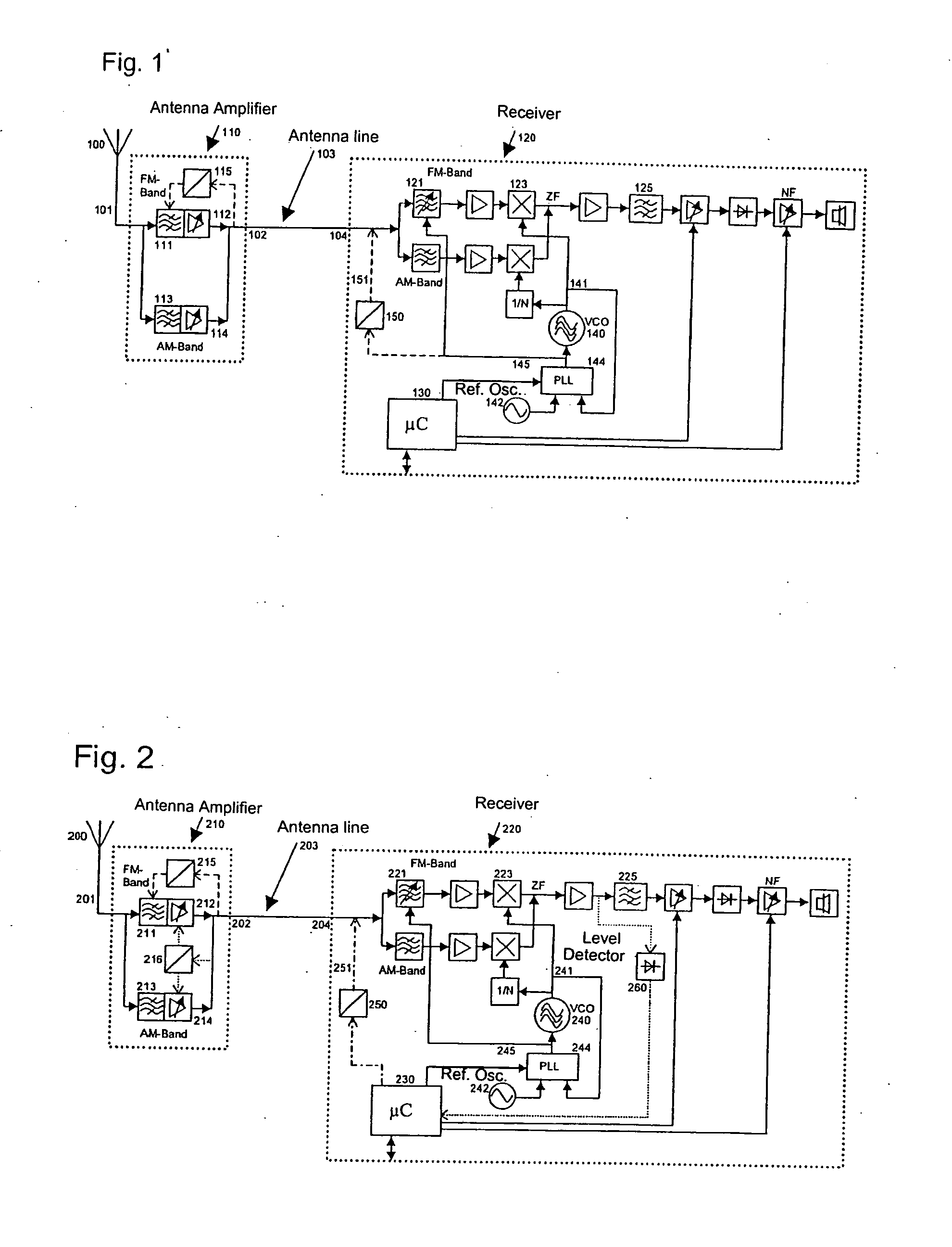
system. In this context, it may be provided that the pass frequency of the filter be tunable via a tuning signal, which is applied to a control terminal of the antenna amplifier and generated by the receiver. Therefore, information items necessary for tuning the filter are transmitted over separate lines. As an alternative, it is provided that the pass frequency of the filter be tunable via a tuning signal, which is applied to the output of the antenna amplifier and generated by the receiver. In this context, the tuning signal, which is applied to the output of the antenna amplifier and evaluated in the antenna amplifier, may be a d.c.
voltage or an
analog signal, e.g., amplitude-modulated, frequency-modulated, or pulse-width-modulated signal, or a
digital data stream. In this connection, the
voltage supply, which may utilize the antenna line as well, may have to be taken into account. In this case, the antenna amplifier may include a device for splitting up or filtering out the signal components at the output. In a further refinement, a supply
voltage for the antenna amplifier may be applied to the output of the antenna amplifier. In this case, the impedance-matched and amplified, useful signal of the antenna, the tuning signal, and the supply voltage are therefore transmitted over the same antenna line. A
digital data stream may also be transmitted by switching the supply voltage on and off or changing the voltage in accordance with the digital coding. An energy store in the antenna amplifier, e.g., a
capacitor or an
inductance coil, powers the antenna amplifier for the duration of the supply-voltage shutoff.
[0008] In one example embodiment of the antenna amplifier, the device for splitting up the signal components also includes, at the output, a storage unit for storing tuning information. In this manner, a plurality of settings may be temporarily stored, for example, in the form of the charging of several capacitors to different voltage values, or as digital information in an open-
loop control module. This is particularly advantageous when the receiving frequency should be rapidly changed or changed for a short period of time, e.g., in the case of so-called RDS skips, and the transmission of the tuning information over the antenna line occurs very slowly in comparison to this.

